
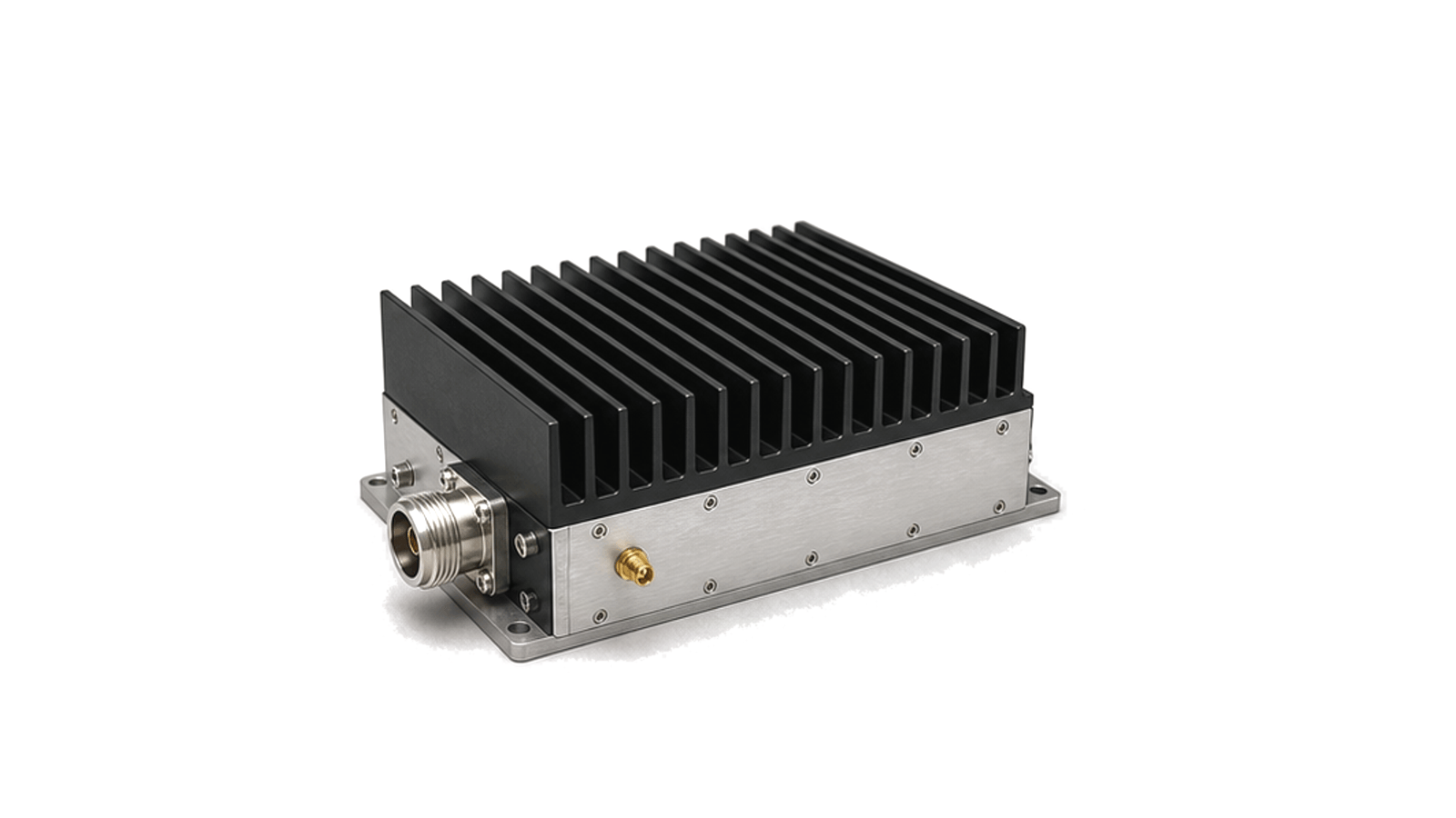
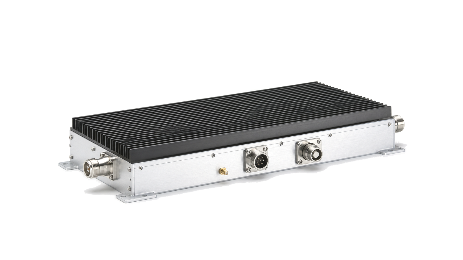
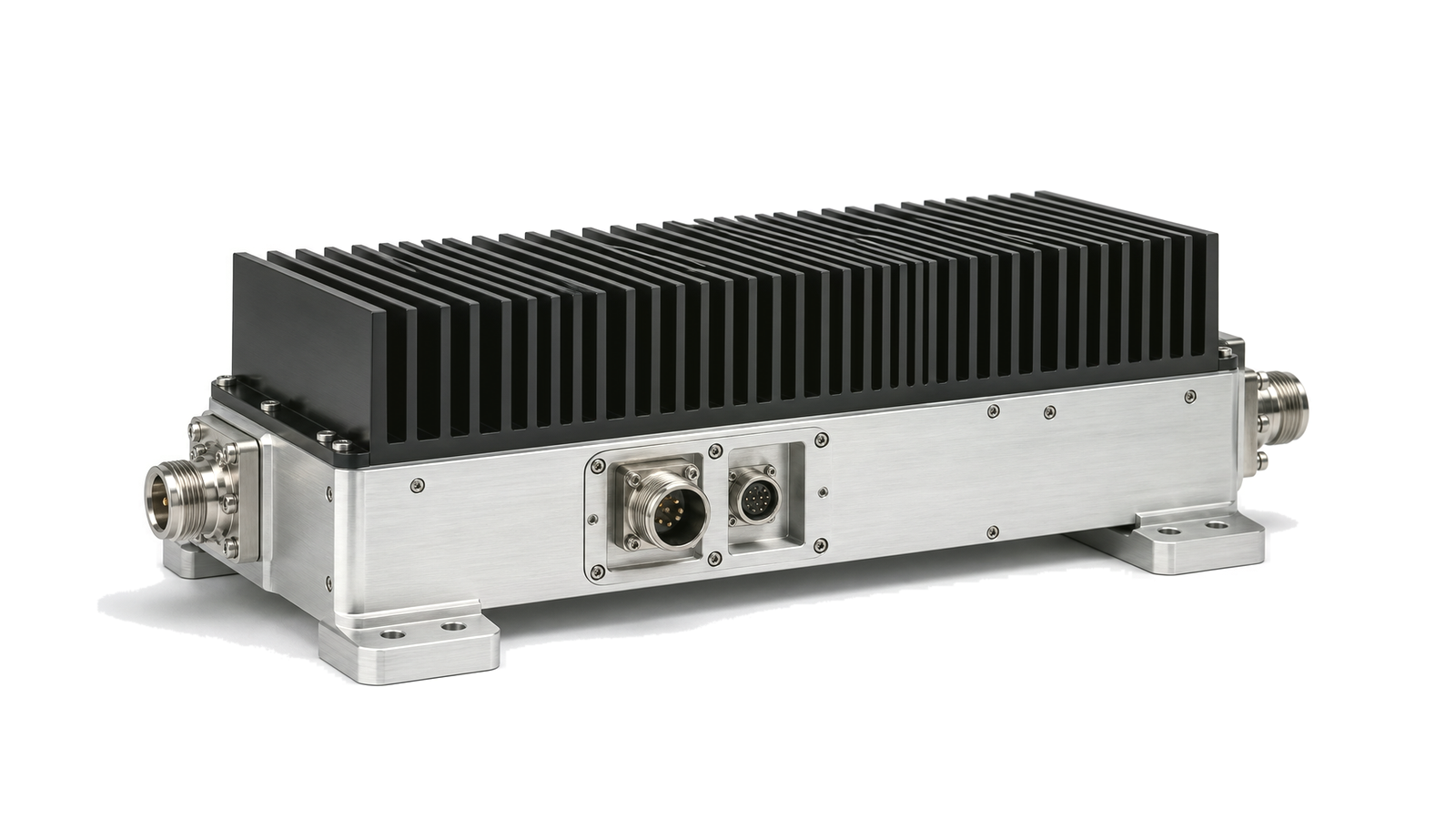
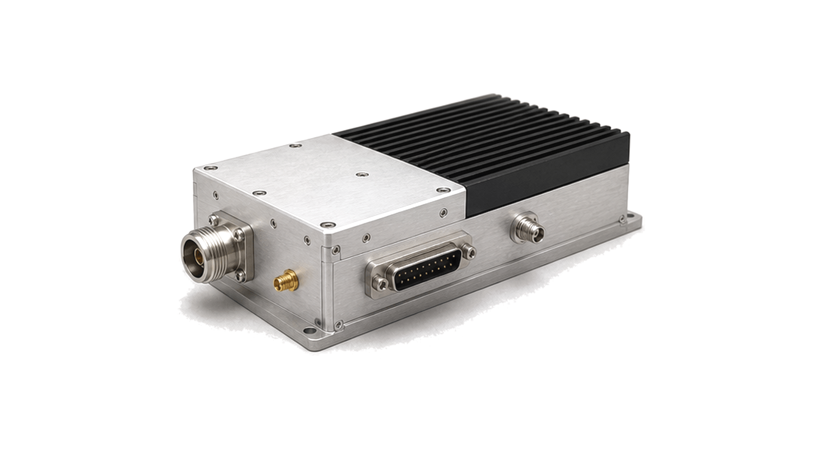
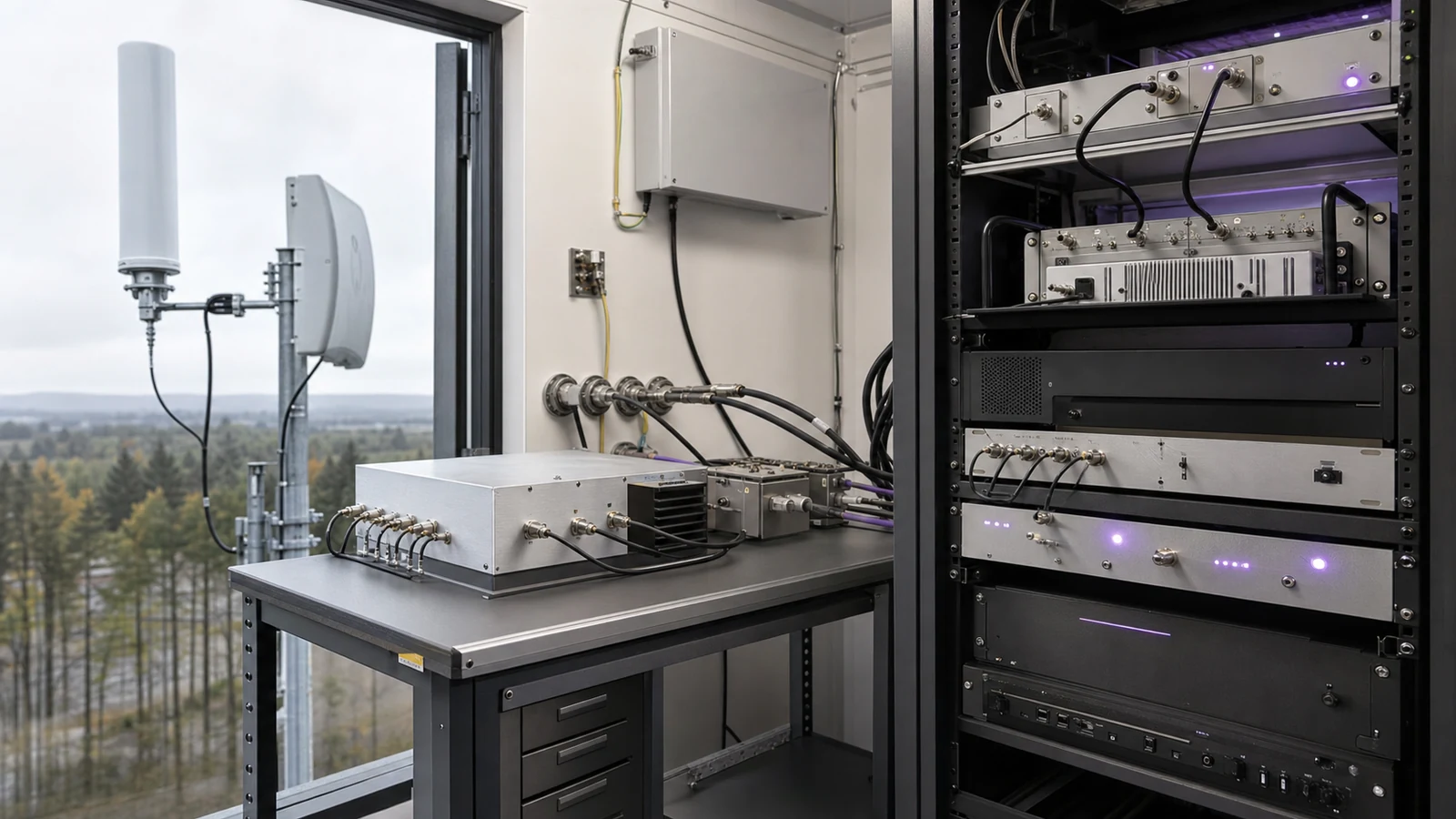
What are RF amplifiers and gain-chain components?
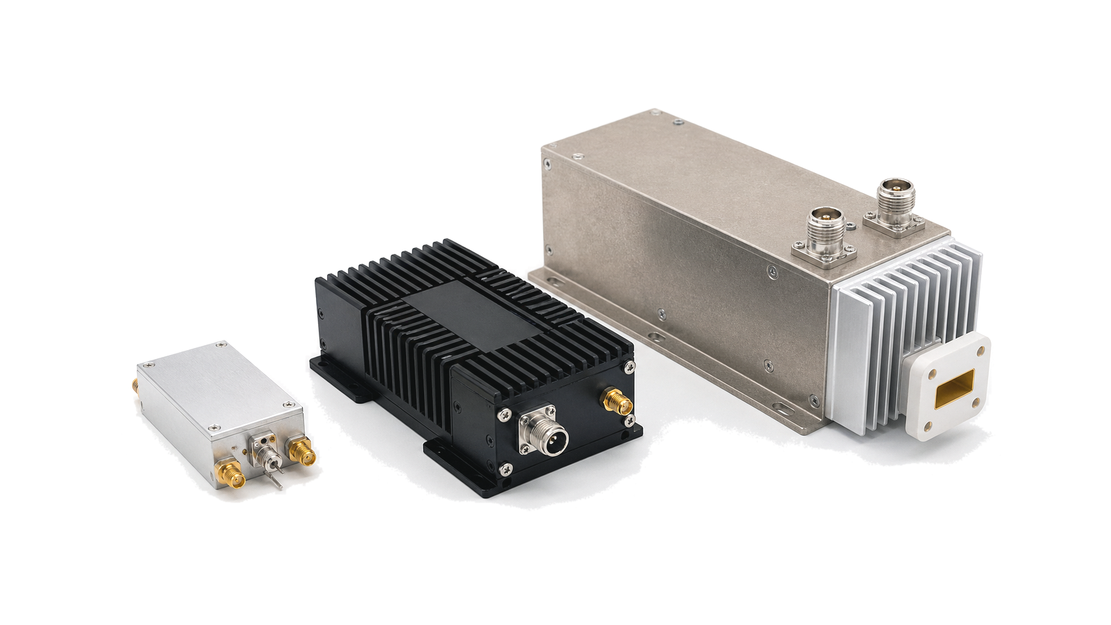
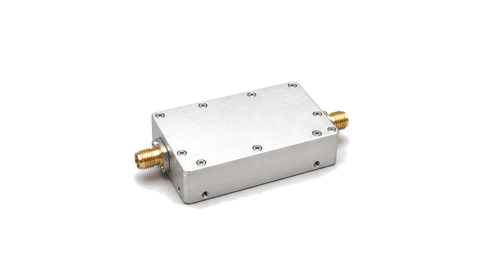
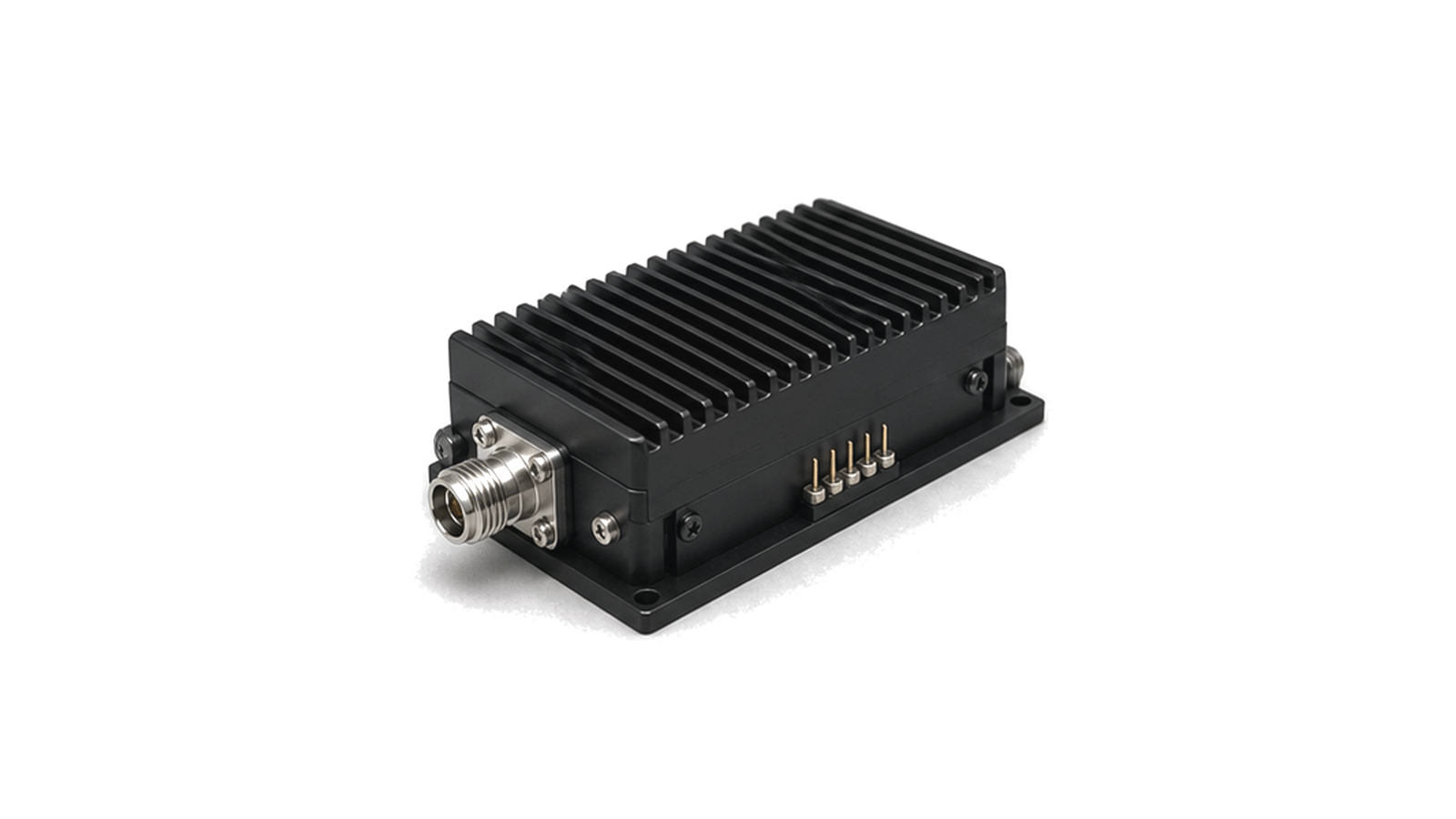
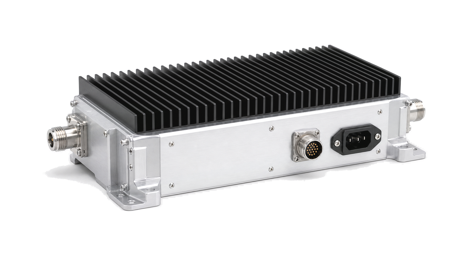
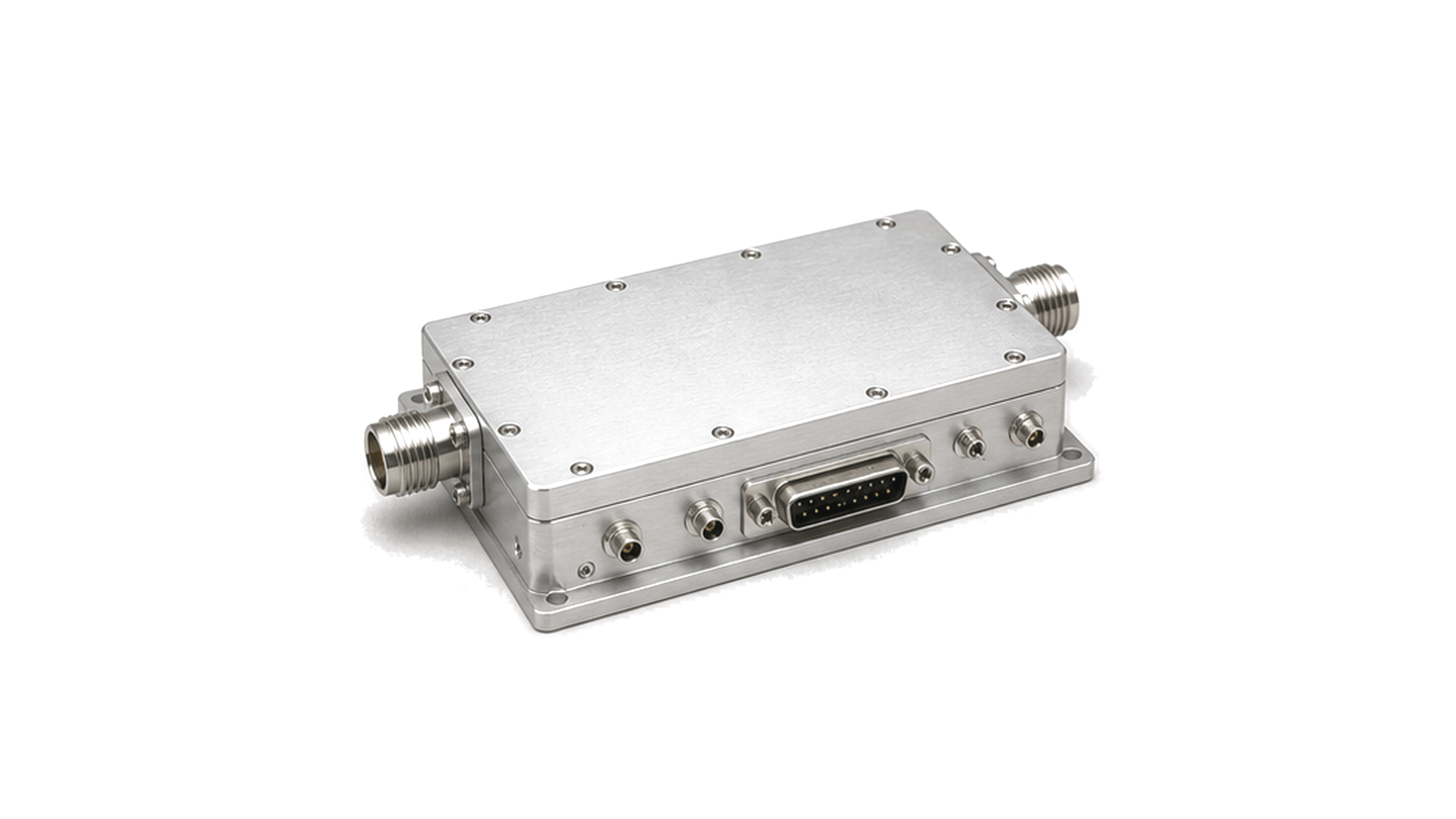
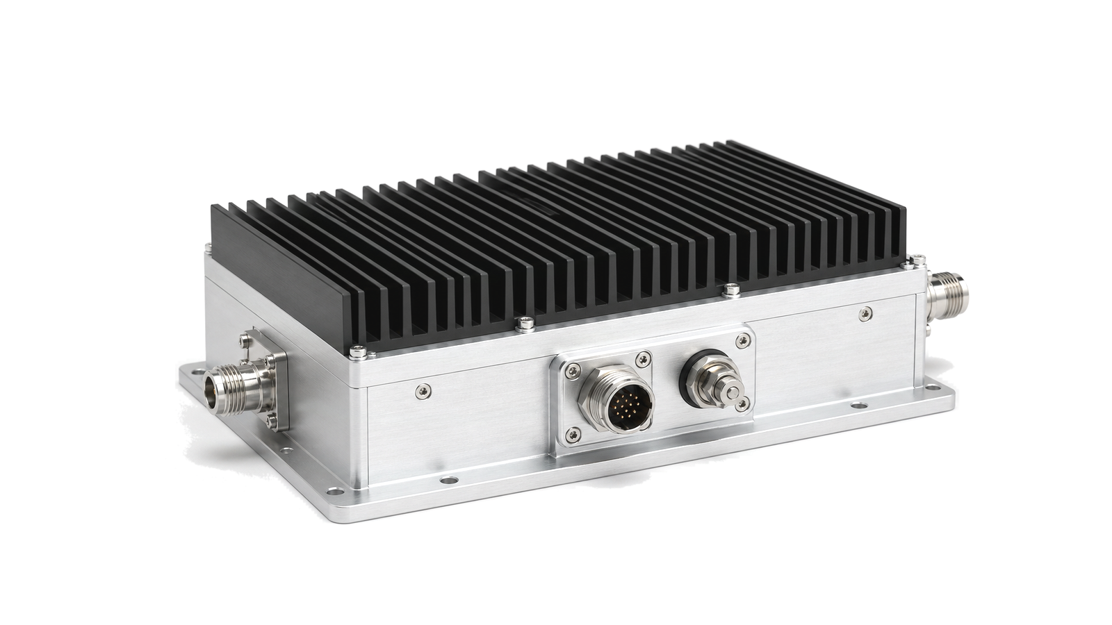
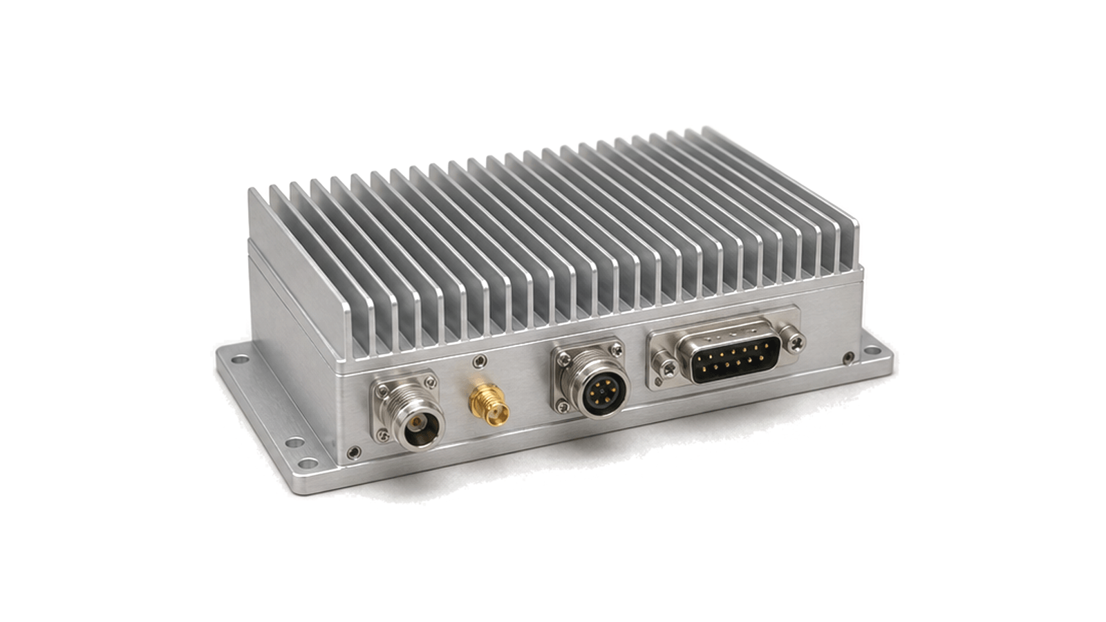
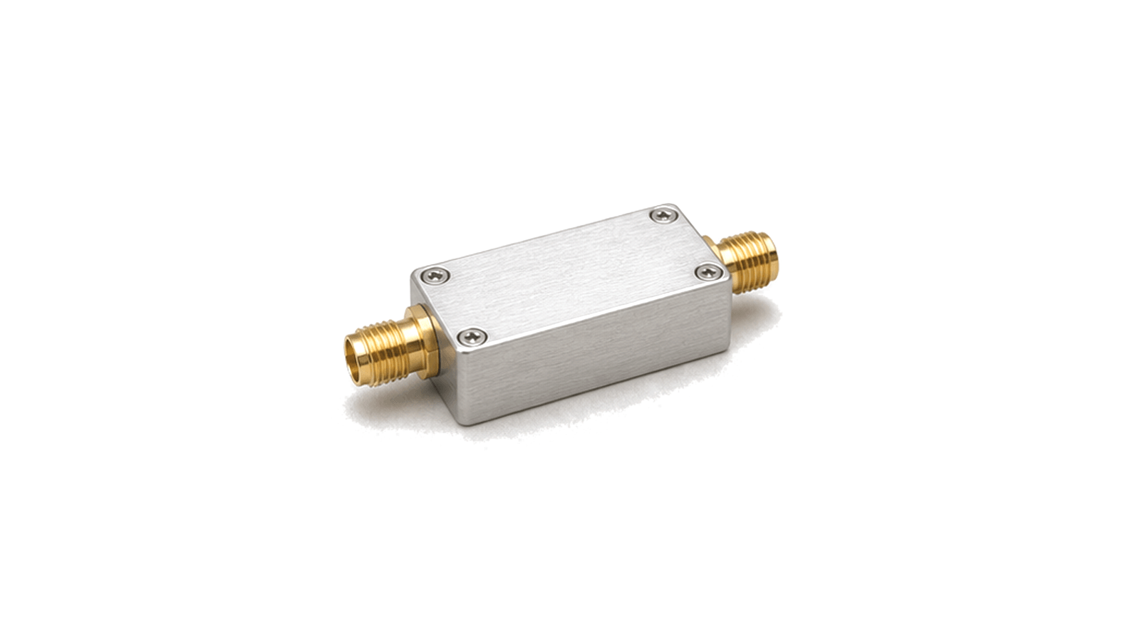
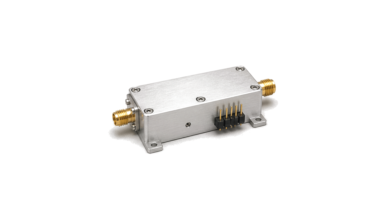
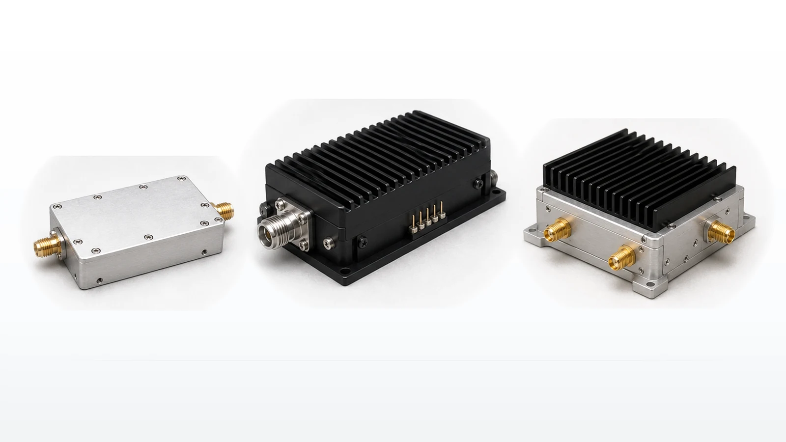
RF amplifiers increase or regulate signal level at a defined point in a receiver, transmitter or measurement path. A gain chain can include a low-noise amplifier near the receive input, gain blocks or variable-gain stages for level control, driver amplifiers for the next active stage and power amplifiers that deliver RF energy to a filter, feed network, load or antenna. The correct family depends on signal-chain position; gain alone does not establish suitability.
How do you select RF amplifiers for a gain chain?
Start with named input and output reference planes. Record the full operating band, minimum and maximum input, required output, downstream loss and the waveform that must pass through the stage. Use those limits to calculate minimum gain and maximum allowable gain, then check noise, linearity, compression, stability, supply and thermal constraints. Reject a candidate that misses a hard interface or environmental boundary before comparing typical performance.
| Gain-chain role | Primary design concern | Evidence to compare |
|---|---|---|
| Receiver input | Preserve sensitivity while tolerating blockers | Noise figure, gain, input match, OIP3 and stability over band and temperature |
| Driver or gain stage | Deliver controlled drive without compressing adjacent stages | Gain range, flatness, P1dB, output linearity, bias and control behavior |
| Transmit power stage | Meet delivered power and signal-quality limits | Average and peak output, back-off, EVM or ACPR, efficiency, mismatch and thermal data |
| Test or leveling path | Maintain repeatable amplitude across frequency and time | Gain accuracy, adjustment range, settling, drift, return loss and calibration method |
Which RF amplifier technical specifications matter?
Frequency range, gain and output power must be read with their test conditions. For a receive stage, noise figure and strong-signal behavior can dominate the decision. For a driver or power stage, P1dB, saturated output, intermodulation, modulation quality and required operating back-off must be separated. Pulsed designs also require pulse width, repetition rate, duty cycle, droop and switching timing. Supply current, control interfaces, protection behavior, baseplate temperature and cooling assumptions complete the operating boundary.
Do not combine unrelated typical values into one system budget. Gain measured at room temperature, output power at a different frequency and efficiency under another waveform do not form a verified operating point. Compare candidates under one agreed condition set and identify which values are guaranteed, characterized or still require qualification.
How should an RF amplifier supplier or manufacturer be evaluated?
Ask for data for the proposed model that states frequency, bias, temperature, waveform, load and measurement reference plane. Confirm mechanical outline, connectors, control logic, protection, thermal interface and lifecycle status alongside RF performance. For repeat purchases, define which tests are performed on every unit, which records accompany delivery and how revisions are controlled. These checks are more useful than a broad supplier claim because they make the proposed hardware comparable and auditable.
How are RF amplifiers tested and verified?
Verification begins with small-signal gain, flatness, match and stability across the required band and temperature range. Large-signal testing then applies the project waveform and measures delivered output, compression, intermodulation or modulation quality at the intended back-off. Power, current and temperature should be recorded at the same operating point. Where mismatch is credible, define the source and load VSWR, phase coverage, duration and acceptable recovery behavior.
- Operating, guard and survival frequency ranges
- Input range, target output and reference-plane losses
- Gain, flatness, tolerance and adjustment requirements
- Noise, P1dB, OIP3, EVM, ACPR or other role-specific limits
- CW, pulsed or modulated waveform and duty cycle
- Supply, control, monitoring and protection interfaces
- Ambient or baseplate limit, cooling method and mounting interface
- Per-unit acceptance tests and required delivery records
Selection and approval boundary
This category defines amplifier families and the evidence needed to compare them; it does not qualify a specific model. Final approval requires documentation for the proposed model and reproducible results under the project frequency, waveform, load, supply and thermal conditions.