What must an RF signal-chain integration plan define?
A usable RF signal-chain plan fixes the input and output reference planes, then closes frequency, level, noise, linearity, impedance, timing, power, thermal and verification budgets across every block between them. It is not a parts list. The architecture must show what each source, converter, filter, amplifier, attenuator, switch, coupler, detector and interface is required to deliver under the same operating states and test conditions.
Freeze the system boundary before choosing hardware
Name the signal direction, operating bands, channel or waveform bandwidth, minimum and maximum levels, impedance, connector or board interface, control states and environmental limits. Draw conducted, radiated and digital reference planes separately. A gain value at a module connector cannot be compared with EIRP, receiver sensitivity or an ADC full-scale target until losses and reference planes are explicit.
Build one frequency plan for RF, LO, IF and sampling
List every tuning range, injection side, spectral inversion, image, LO feedthrough, harmonic and intermodulation combination that can reach a protected band. Place filtering where it prevents overload as well as where it satisfies final rejection. Include synthesizer step size, lock time, phase noise and reference-clock behavior; a frequency plan that closes only at nominal tuning is not an integration plan.
Close gain, noise and dynamic range by operating state
Create separate cascades for minimum signal, nominal traffic, maximum wanted signal, blockers and fault exposure. Early loss directly degrades receiver noise figure, while excessive early gain can move a mixer, IF stage or converter toward compression. For transmit paths, distinguish small-signal gain, P1dB, saturated power and waveform-linear output. Calculate cascade noise and intercept performance with linear quantities, then verify the result with the actual filters, gain states and blocker frequencies.
Treat impedance, stability and isolation as system properties
Nominal 50-ohm data does not guarantee a stable assembled chain. Review source and load match over frequency and state, especially around high-gain stages, switches, filters, long interconnects and antenna mismatches. Allocate return loss, reverse isolation, port-to-port leakage and permissible VSWR at named planes. Add limiters, attenuators, isolators or damping only when their insertion loss, power and noise consequences are included in the same budget.
Close control, power, timing and thermal interfaces
Bias sequence, enable timing, switching transients, detector latency, gain-state control, fault thresholds and safe shutdown determine whether the RF path reaches its specified state. Rail ripple and converter clocks can create spurs or phase-noise sidebands. Model dissipation for simultaneous channels, duty cycle, ambient temperature, airflow or conduction path, then connect junction or case limits to gain drift, phase drift, output backoff and calibration interval.
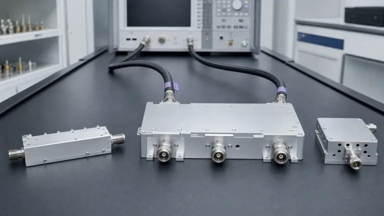
Verify the chain at the contractual reference planes
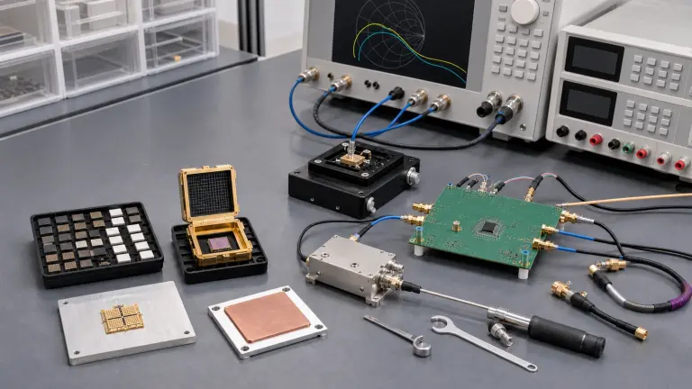
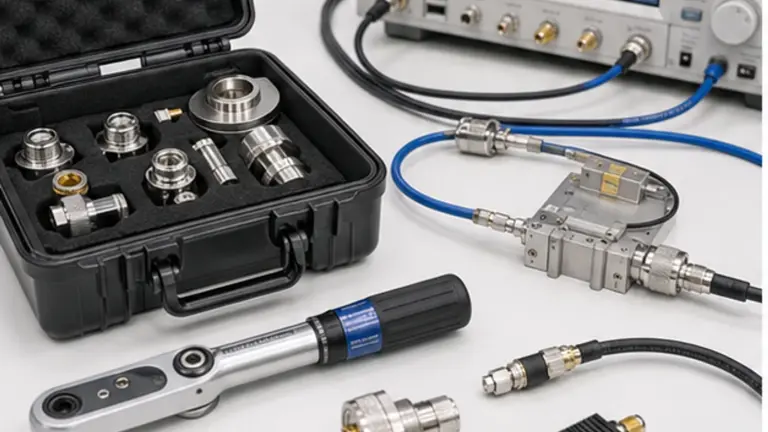
Start with calibrated S-parameters, gain, noise, compression and two-tone measurements for individual blocks. De-embed cables, fixtures and adapters to the agreed planes. Then exercise the assembled path across frequency, temperature, supply, gain state, waveform, blocker level, mismatch and switching sequence. Store calibration state, uncertainty, firmware, configuration and pass/fail limits with each result so production acceptance can reproduce the engineering evidence.
Minimum allocation record for an integrated RF path
| Budget area | Required project input | Acceptance evidence |
|---|---|---|
| Frequency and spurs | RF/LO/IF ranges, injection, bandwidth, protected bands | Tuning table, spur search and filter-state results |
| Levels and noise | Input range, gain states, NF, sensitivity and blocker levels | Cascade file plus calibrated gain and noise measurements |
| Linearity and power | Waveform, PAPR, P1dB, IP3, EVM or spectral limits | Compression, two-tone and modulated-signal results |
| Interfaces | Impedance, return loss, connectors, control, power and timing | S-parameters, sequence log and interface drawing |
| Environment | Temperature, duty cycle, cooling, mismatch and faults | Thermal map, derating curve and fault-recovery record |
RFQ inputs that prevent an avoidable redesign
- Signal direction, operating bands, tuning range, channel bandwidth and waveform
- Named input, output, antenna, converter and measurement reference planes
- Minimum, nominal, maximum and blocker levels for every operating state
- Gain, noise figure, sensitivity, compression, IP3, EVM and spur limits
- RF/LO/IF plan, injection side, images, harmonics and protected frequency regions
- Impedance, connector, return loss, VSWR, isolation and leakage requirements
- Supply rails, sequencing, control protocol, timing, telemetry and safe states
- Duty cycle, ambient range, cooling path, mechanical envelope and qualification
- Calibration method, uncertainty, test fixtures, acceptance limits and data format
Solution boundary
The engineering scope covers the architecture and integration of a conducted or radiated RF path across multiple functional blocks. It does not replace a product datasheet, antenna-site design, propagation study, regulatory certification or a detailed production test procedure. Those become separate work packages after the signal-chain reference planes and budgets are approved.
What must an RF signal-chain integration plan define?
- RF Signal Chain Design & Integration architecture
- Freeze the system boundary before choosing hardware Name the signal direction, operating bands, channel or waveform bandwidth, minimum and maximum levels, impedance, connector or board interface, control states and environmental limits. Draw conducted, radiated and digital reference planes separately....
- RF Signal Chain Design & Integration design requirements
- Build one frequency plan for RF, LO, IF and sampling List every tuning range, injection side, spectral inversion, image, LO feedthrough, harmonic and intermodulation combination that can reach a protected band. Place filtering where it prevents overload as well as where it satisfies final rejection....
- RF Signal Chain Design & Integration integration
- Close gain, noise and dynamic range by operating state Create separate cascades for minimum signal, nominal traffic, maximum wanted signal, blockers and fault exposure. Early loss directly degrades receiver noise figure, while excessive early gain can move a mixer, IF stage or converter toward compression....
- RF Signal Chain Design & Integration test and verification
- Treat impedance, stability and isolation as system properties Nominal 50-ohm data does not guarantee a stable assembled chain. Review source and load match over frequency and state, especially around high-gain stages, switches, filters, long interconnects and antenna mismatches. Allocate return loss, reverse isolation, port-to-port leakage and permissible VSWR at named planes....