RF amplifier selection answer
Select an RF amplifier by defining the operating band and system reference planes first, then calculate required gain from the worst-case input, target output and path loss. Verify average and peak output, P1dB back-off, linearity, noise, waveform duty cycle, supply and thermal boundaries under equivalent test conditions. Reject candidates that fail an interface or environmental limit before comparing headline performance.

RF amplifier decision matrix
The first comparison should separate mandatory limits from optimization targets. A candidate that misses a mandatory frequency, interface, voltage, environmental or lifecycle boundary should not receive a weighted score.
| Decision | Required project evidence | Reject when |
|---|---|---|
| Frequency coverage | Operating band, sub-bands, guard bands, blockers and temperature range | Gain, match or stability is not demonstrated across the complete band |
| Gain | Minimum and maximum input, target output, downstream loss and tolerance | Minimum gain misses the target or maximum gain overdrives this or the next stage |
| Output and linearity | Average power, peak envelope power, PAPR, EVM, ACPR or intermodulation limit | The required quality is not verified at the stated back-off |
| Noise and blockers | Receiver sensitivity, cascaded noise budget, blocker levels and OIP3 target | Noise or strong-signal behavior breaks the receiver budget |
| Thermal boundary | CW, pulsed or modulated waveform, duty cycle, ambient/baseplate and cooling | Sustained dissipation is not supported under the actual mounting boundary |
| Interfaces | Supply, control, protection, connectors, outline and environmental limits | An external dependency or mechanical constraint is incompatible |
Where should the RF requirement be defined?
Define gain and power at named system reference planes, not at whichever connector makes a data sheet look favorable. Record what sits before and after the amplifier, including cables, filters, switches, couplers and fixtures. Their insertion loss and variation belong in the chain budget. State source and load impedance, expected mismatch, switching transients and whether the load can be unknown or disconnected.
How much gain margin should an RF amplifier chain include?
There is no universal gain-margin value; derive it from worst-case input, target output, path loss, device tolerance and temperature drift. Calculate the minimum gain needed at the lowest input, then verify that maximum input plus maximum gain does not compress this stage or the next. Keep manufacturing and temperature allowance separate from linearity back-off.
Cover the complete operating band
Minimum and maximum frequency are not enough when a system has sub-bands, guard bands, harmonics or strong out-of-band blockers. Compare gain flatness, input and output return loss, unconditional or conditional stability and usable linearity over frequency and temperature. A center-frequency typical value cannot establish full-band suitability.
Worked gain, back-off and thermal example
Assume a driver provides +10 dBm. The antenna feed requires +37 dBm average, and the filter plus cable after the amplifier loses 1.5 dB. The amplifier must therefore deliver +38.5 dBm average, so the nominal gain requirement is:
Required gain = 38.5 dBm - 10 dBm = 28.5 dB.
If the waveform has 7 dB PAPR and the project reserves 2 dB additional linearity margin, the peak linear output target becomes +47.5 dBm. A P1dB value near +47.5 dBm is only an initial screen; EVM or ACPR must still be measured with the real waveform at the required average output. At +38.5 dBm, RF output is about 7.1 W. With 25% power-added efficiency as a planning assumption, DC input is roughly 28 W and heat to remove is approximately 21 W. Replace the assumed efficiency with measured data before final thermal design.

Which linearity and noise values matter?
The relevant metric depends on the amplifier's signal-chain role and waveform. A receiver-front-end stage places greater weight on noise figure, gain and blocker tolerance; a driver or transmit stage places greater weight on output-referred linearity, compression and delivered power. P1dB marks the onset of meaningful gain compression, while saturated power describes a more nonlinear limit. Neither proves modulated-signal quality by itself.
What is the difference between P1dB and saturated output power?
P1dB is the compression point where small-signal gain has fallen by 1 dB; saturated output power is a higher, strongly nonlinear limit. A modulated or linear system normally operates below P1dB by the back-off required for EVM, ACPR or intermodulation performance. Saturated power is not a linear delivered-power rating.
Compare equivalent conditions
Require frequency, bias, temperature, input level, load, waveform bandwidth and measurement reference plane beside every critical number. Do not combine typical values measured under unrelated conditions into a guaranteed system budget. When only typical performance is available, record the qualification test or engineering margin that will close the uncertainty.

What thermal and duty-cycle data are required for an RF power amplifier?
Waveform determines both peak linearity demand and sustained thermal load. A pulsed requirement needs pulse width, repetition frequency, duty cycle, rise/fall time, droop and gating timing. A modulated requirement needs bandwidth, PAPR and quality limits. A CW requirement needs sustained output, ambient or baseplate limits and the complete cooling boundary. Size the supply from driven current and transient behavior, not only quiescent current.

Common selection failures
- Comparing center-frequency gain while ignoring band-edge flatness, match or stability.
- Using saturated power as the normal linear output rating for a modulated waveform.
- Adding an arbitrary gain margin without checking the maximum-input compression case.
- Quoting pulsed peak power without pulse width, repetition rate and duty cycle.
- Accepting a thermal result that depends on an unspecified heatsink or baseplate temperature.
- Mixing fixture loss and system cable loss into the amplifier specification.
- Comparing typical curves as though they were production acceptance limits.

Minimum RF amplifier RFQ checklist
- Operating, guard and survival frequency ranges
- Minimum and maximum input at named reference planes
- Required gain, flatness, tolerance and adjustment method
- Average output, peak output, PAPR and linearity or signal-quality limit
- CW, pulsed or modulated waveform details and duty cycle
- Source/load match, expected VSWR and mismatch behavior
- Supply voltage, driven current, sequencing, enable, monitoring and protection
- Ambient/baseplate limits, cooling method and mounting interface
- Outline, connectors, keep-outs, mass and environmental requirements
- Per-unit acceptance tests, qualification evidence, quantity and lifecycle expectation
Method, evidence and approval boundary
This guide is a requirement-definition and candidate-screening method, not a qualification statement for a specific model. Build gain, power, linearity and thermal limits at named reference planes, compare candidates under one project condition set, then approve a model only from model-level documentation and reproducible tests.
- Engineering method
- Reference-plane budgeting, hard-gate rejection, waveform and back-off checks, thermal-boundary review and interface compatibility.
- Visual status
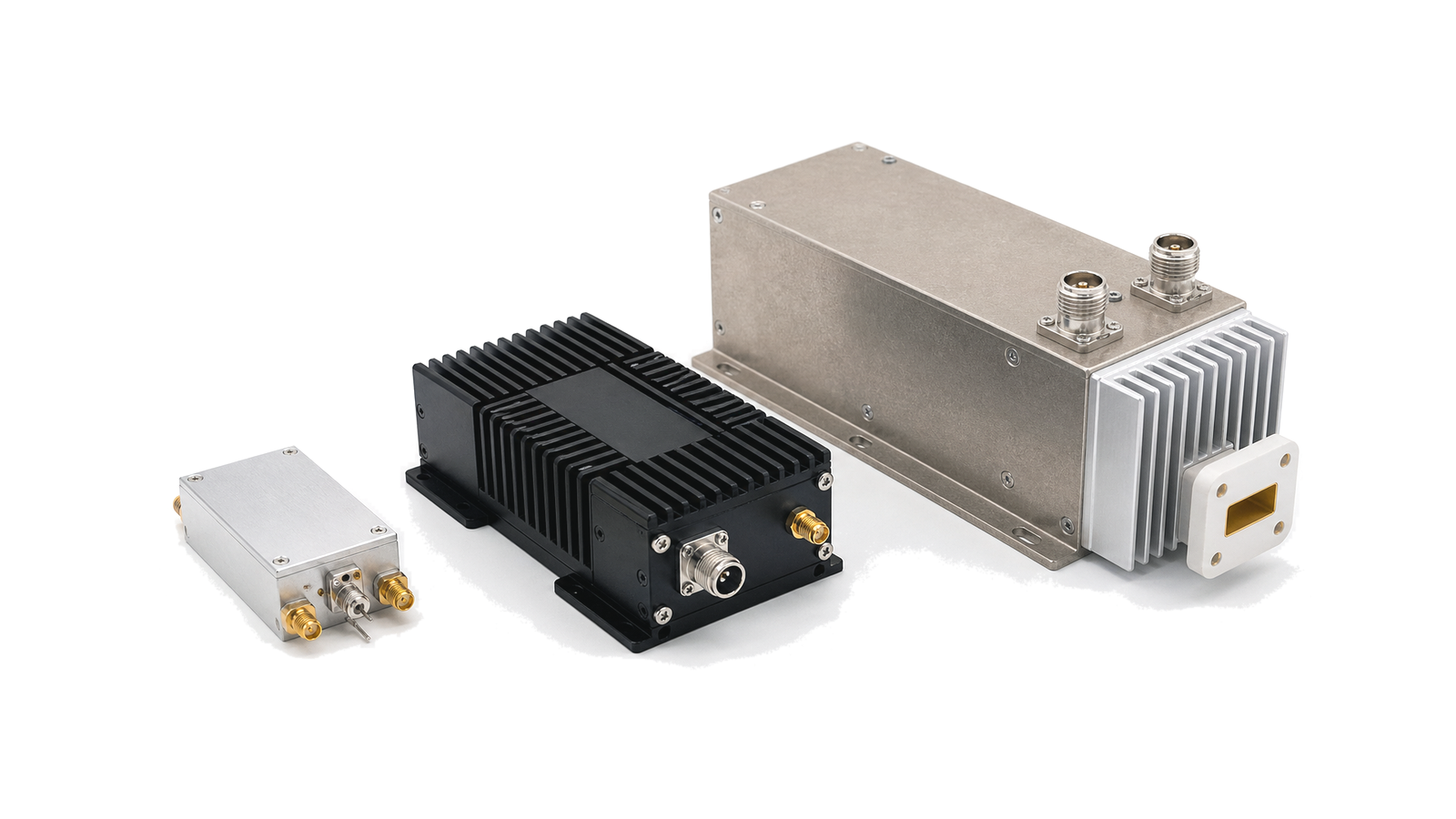
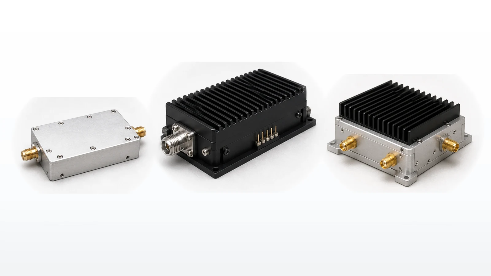
- Contextual photographs are illustrative configurations and technical diagrams explain relationships. Neither is a measured product record or evidence for a performance claim.
- Approval evidence
- A data sheet with test conditions, model-specific characterization or acceptance data, mechanical and thermal interfaces, compliance records and project pass/fail limits.
Technical review and revision record
| Review date | Review owner | Scope of this revision |
|---|---|---|
| 2026-07-12 | LCRF RF Systems Review | Direct answer, decision matrix, worked calculation, failure modes, evidence boundary, image status, related products and inquiry path. |
Continue the RF amplifier decision
Use the related LCRF pages below to compare available product families, resolve a specific engineering question or send the project conditions for review.