Treat the installed item as one controlled RF boundary
A defensible transportation RF specification connects the antenna, body or ground plane, feedthrough, cable, protection, RF electronics, vehicle power, bonding, mounting, cooling and service evidence to one named configuration. The platform changes electrical and RF behavior: cable loss and delay move with route and temperature, bodywork reshapes the antenna pattern, supply wiring creates transients and ground offsets, nearby radios create simultaneous-signal stress, and maintenance changes connector and harness states. Selection therefore starts with installation drawings and operating modes, not a family name.
Name the platform, mounting zone and exact installed item
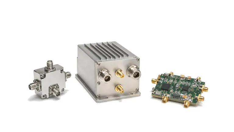
State whether the item is a component, remote front end, radio enclosure, antenna subsystem, cable assembly, line-replaceable unit or complete installed path. Identify rail vehicle, wayside cabinet, vessel, road vehicle, test fleet or aircraft context; mounting location; structural material; indoor, exterior or pressurized zone; access interval; service life; repair concept; and consequence of loss. The same enclosure can face different vibration, ingress, thermal, bonding and approval decisions when it moves from a protected cabinet to a roof, mast, underfloor bay or airborne compartment.
List startup, normal receive, transmit, simultaneous transmit and receive, standby, calibration, degraded, shutdown, maintenance and credible fault states. For each state record active ports, waveform, peak and average duty, supply state, data traffic, thermal boundary and required recovery. Separate survival, continued operation and retained RF performance. Phrases such as vehicle grade, railway compliant or ruggedized do not define the mounting category, item boundary or measurable result.
Freeze antenna, feedthrough, coax route and installed RF reference planes
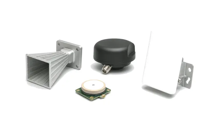
Define antenna type, polarization, pattern objective, mounting height and orientation, ground-plane or counterpoise dimensions, radome, body cutout, keep-out region, separation from other antennas and representative surrounding metal. Mark the feedthrough, surge or ESD protection, filter, bias feed, cable segments, adapters, rotary or flexible sections and RF electronics on one controlled drawing. A free-space antenna pattern or a module connector measurement cannot be treated as installed coverage or immunity evidence when the body, roof, mast, window, cable and nearby transmitters are outside the reference boundary.
Allocate loss, return loss or VSWR, power, noise figure, linearity, isolation, phase and delay at named planes across frequency, temperature, bend state, mating cycles and manufacturing tolerance. Record cable construction, length, minimum bend radius, clamp spacing, connector family, torque, strain relief, drainage, abrasion protection and replacement rule. Preserve the service loop only when it does not violate bend or phase-stability limits. For multi-radio platforms, define antenna-to-antenna coupling and simultaneous blocker or intermodulation cases instead of qualifying each radio alone.
Specify platform power, return, bonding and control as measured interfaces
At the RF hardware terminals, define nominal and continuous voltage range, crank or brownout where applicable, dropouts, surges, load dump or switching transients, ripple, inrush, reverse polarity, sequencing, hold-up, overcurrent, fault energy and recovery. State source impedance and harness resistance and inductance, because a transient measured at the distribution unit is not automatically the transient seen at the equipment. Separate functional supply, chassis, RF shield and signal returns; then show where they join and how unintended ground loops are prevented.
Define bond path, material stack, finish, fastener, contact preparation, torque, corrosion control and maximum verified impedance at the relevant frequency range. Include shield termination, connector backshell, enclosure seams, antenna base and cable protection in the EMC boundary. Control enable, Ethernet, serial, timing and discrete interfaces with common-mode range, isolation, shielding, pin state during startup and fault behavior. Passing a bench supply test does not prove operation on a long vehicle harness with shared loads and switching noise.
Tailor environment, mechanics and thermal limits to the real location
Build a location-specific exposure profile for storage, shipment, depot handling, installation, operation, cleaning and maintenance. Define temperature and rate of change, solar load, altitude or pressure, humidity and condensation, salt, water, dust, fluids, icing, shock, vibration spectrum and axes, mounting stiffness, cable mass, connector loads and expected cycles. Rail vehicle, road vehicle, vessel and airborne references describe different scopes; even within one platform, roof, cab, engine bay, rack and protected cabin are not interchangeable categories.
Tie electrical operation to the thermal and mechanical setup. State baseplate or air temperature, airflow, conductive interface, dissipated power, transmit duty, nearby heat sources, enclosure orientation and allowable case or junction proxy. Monitor RF function, supply current, alarms and connector continuity during exposure when the requirement calls for operation, then repeat calibrated end-to-end measurements after exposure. A visual inspection alone can miss phase drift, intermittent contact, filter detuning, compression loss or moisture-related leakage.
Verify EMC and radio coexistence in the configured harness and operating states
Define conducted and radiated emissions and immunity at the intended equipment boundary with representative cables, lengths, terminations, loads, enclosure, bonding and software state. Identify victim functions and degradation criteria: loss of link, reset, false alarm, timing error, data corruption, gain shift or delayed recovery. Record antenna-port and cable-injection methods separately from enclosure-field exposure. Standard methods provide test frameworks, but applicability and severity still depend on platform category, installation and authority.
Create a simultaneous-signal matrix for every onboard transmitter and susceptible receive path. Include frequency separation, harmonic and intermodulation products, transmit power and duty, antenna isolation, filter state, LNA compression, recovery time and permitted degradation. Verify worst credible combinations at defined planes, not only nominal channels. If compliance or type approval is required, name the approving route and evidence owner; do not convert a component test into a vehicle, vessel, rolling-stock or aircraft approval claim.
Close verification, maintenance and lifecycle change control
Map each requirement to inspection, analysis, demonstration or test; state the level, article serial, hardware and firmware revision, antenna and cable configuration, power source, mounting, fixture, environment, operating mode, uncertainty and pass criterion. Sequence baseline RF characterization, power and interface tests, EMC and simultaneous-signal checks, environmental exposure and final end-to-end verification so damage and drift are observable. Qualification, type testing, design verification, production acceptance and installation commissioning are different evidence sets and must not be used interchangeably.
Design for inspection, connector access, cable replacement, drainage, torque confirmation, firmware loading and calibration without disturbing unrelated paths. Define approved spares, shelf life, preventive inspection, wear limits, calibration interval, field diagnostic data and replacement triggers. Every change to antenna, cable, connector, filter, power protection, enclosure, firmware, mounting or supplier needs an impact assessment and named re-verification. The delivery package should identify exactly which installed configurations the evidence supports and which claims remain project-specific.
| Decision boundary | Requirement to freeze | Reject the proposal when |
|---|---|---|
| Platform and zone | Platform class, location, structural material, exposure, access, service life and exact installed item | Mobile grade or rugged replaces a location definition |
| Antenna installation | Pattern objective, polarization, ground plane, radome, keep-out, body cutout and nearby antennas | Only a free-space antenna data sheet is offered |
| Feed and RF path | Feedthrough, protection, cable type and route, connectors, loss, match, delay, power and reference planes | Cable length, bend state or mating condition is unknown |
| Power and grounding | Terminal voltage, source impedance, transients, inrush, returns, shields, bond path and recovery | A bench supply result is used for a vehicle harness |
| Environment and thermal | Location-specific temperature, ingress, fluids, shock, vibration, mounting, duty and cooling | A platform standard is cited without category or severity |
| EMC and coexistence | Harness, enclosure, bonds, modes, simultaneous radios, victim functions and degradation criteria | Each radio is tested alone in an ideal cable setup |
| Verification identity | Serial, BOM, firmware, antenna, cable, mounting, power source, methods, raw results and uncertainty | Evidence was generated for a different installed configuration |
| Service and lifecycle | Access, inspection, spares, wear, calibration, diagnostics, substitutions and re-test triggers | Maintenance or alternate parts can change the path without review |
Worked decision: a roof antenna and eight-metre feed are part of the radio
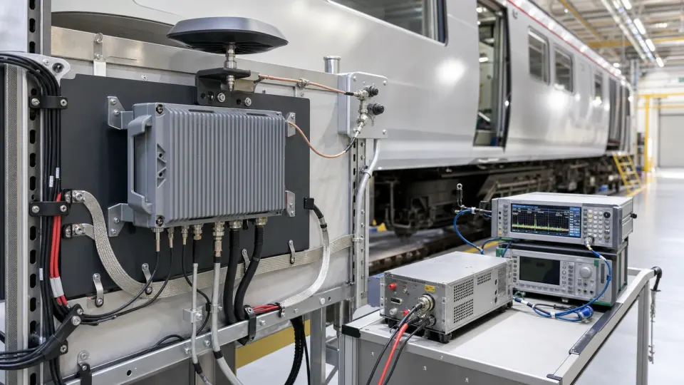
Consider a roof antenna connected through a panel feedthrough and eight metres of coax to a cabinet-mounted RF front end. The radio meets sensitivity on a short bench cable, but the installed cable loss and delay vary with temperature, the roof panel changes the antenna pattern, a nearby transmitter compresses the LNA, and a long DC harness produces a startup dip and conducted transient. The controlled specification names the antenna ground plane and keep-out, feedthrough and protection, cable construction and route, loss and delay limits, connector torque and clamp state, RF and DC terminal planes, source impedance, bond path, simultaneous-transmit cases and service access. Verification measures the baseline installed chain, applies the declared power and EMC stresses in representative harness and operating states, repeats RF performance after environmental exposure, and ties every result to antenna, cable, firmware, mounting and enclosure revisions. The short-cable bench result remains a component datum; it is not installation acceptance evidence.

Build the installed-platform verification flow
- Approve platform, mounting zone, installed-item boundary, operating modes, service life, maintenance concept and applicable authority.
- Freeze antenna location, ground plane, radome, keep-out, feedthrough, protection, cable route, connectors and RF reference planes.
- Allocate gain or loss, noise, power, linearity, isolation, match, phase and delay across temperature, tolerance and installation states.
- Define terminal power range, source impedance, inrush, dropouts, transients, ripple, sequencing, fault energy and recovery.
- Approve return, shield, chassis bond, corrosion protection, cable support, mounting and thermal-interface drawings.
- Tailor environmental and mechanical exposures to the exact location, axes, severity, duration, operating state and pass criteria.
- Build the EMC and simultaneous-radio matrix with representative harnesses, loads, software states and degradation limits.
- Baseline article serial, BOM, firmware, antenna, cable, mounting, fixtures, instruments, calibration and uncertainty.
- Run interface, RF, power, EMC and environmental verification, then repeat end-to-end measurements and resolve anomalies.
- Deliver raw data, configuration index, inspection and maintenance limits, open actions, substitution controls and re-test triggers.
Failures hidden by a mobile-platform label
- Selecting a radio before defining mounting zone, antenna body effects and cable route
- Using a free-space antenna pattern as installed coverage evidence
- Ignoring cable delay, temperature, flexure, clamp state, connector torque and mating cycles
- Applying a distribution-unit transient directly to equipment terminals without harness impedance
- Combining functional return, shield and chassis paths without a controlled bonding diagram
- Citing a rail, automotive, marine or airborne standard without category, severity or operating state
- Testing radios one at a time and missing blocker, intermodulation and recovery cases
- Qualifying one hardware, firmware or harness configuration and shipping another
- Designing an installation that cannot be inspected or serviced without disturbing adjacent paths
- Approving a replacement antenna, cable, filter or protection device without impact analysis and re-verification
Information required for a transportation RF hardware RFQ
- Platform type, route or service context, mounting zone, structural material and exact installed-item boundary
- Normal, transmit, receive, simultaneous, standby, startup, shutdown, maintenance and fault operating states
- Frequency bands, waveforms, bandwidths, channel plan, duty, peak and average power and coexistence transmitters
- Antenna type, polarization, pattern objective, ground plane, radome, keep-out, spacing and mounting drawing
- Feedthrough, surge or ESD protection, filter, cable construction and length, connectors, bend, clamp and torque rules
- RF reference planes and limits for loss, match, gain, noise, linearity, isolation, phase, delay and recovery
- Terminal voltage, source impedance, inrush, dropouts, transients, ripple, sequencing, reverse polarity and protections
- Return, shield, bond and ground architecture, material finishes, corrosion control and verified bond limits
- Data, control, timing, telemetry and discrete interfaces, startup pin states, isolation and fault behavior
- Storage, transport, operational temperature, pressure, humidity, condensation, water, dust, salt, fluids and icing
- Shock, vibration spectra and axes, mounting stiffness, cable mass, connector loads, cycles and thermal boundary
- EMC methods, installation category, harness and enclosure setup, simultaneous-radio matrix and degradation criteria
- Verification article, serial identity, BOM, firmware, fixtures, instrumentation, uncertainty, raw data and pass criteria
- Maintenance access, inspection, diagnostics, spares, calibration, wear limits, lifecycle notices and re-test triggers
Related transportation RF application and solution paths
- Review transportation and mobility RF applications
- Review rail communications RF hardware
- Review maritime communications and radar hardware
- Review connected-vehicle RF integration
- Review airborne RF platform applications
- Review antenna feed and matching solutions
- Review remote RF front-end assembly solutions
- Send the installation, power, EMC and lifecycle requirements