
LCRF

Privacy preferences

Choose optional purposes independently. You can change or withdraw your choice at any time from the footer.

Strictly necessary

Required for security, session functions and storing your privacy choice.

Always active
Preferences

Remembers optional display or language settings when these features are enabled.

Analytics

Uses first-party visitor and session identifiers to measure pages, referrals and inquiry interactions.

Marketing

Allows marketing measurement or third-party advertising technologies if they are introduced in the future.

RF Sensing & Imaging

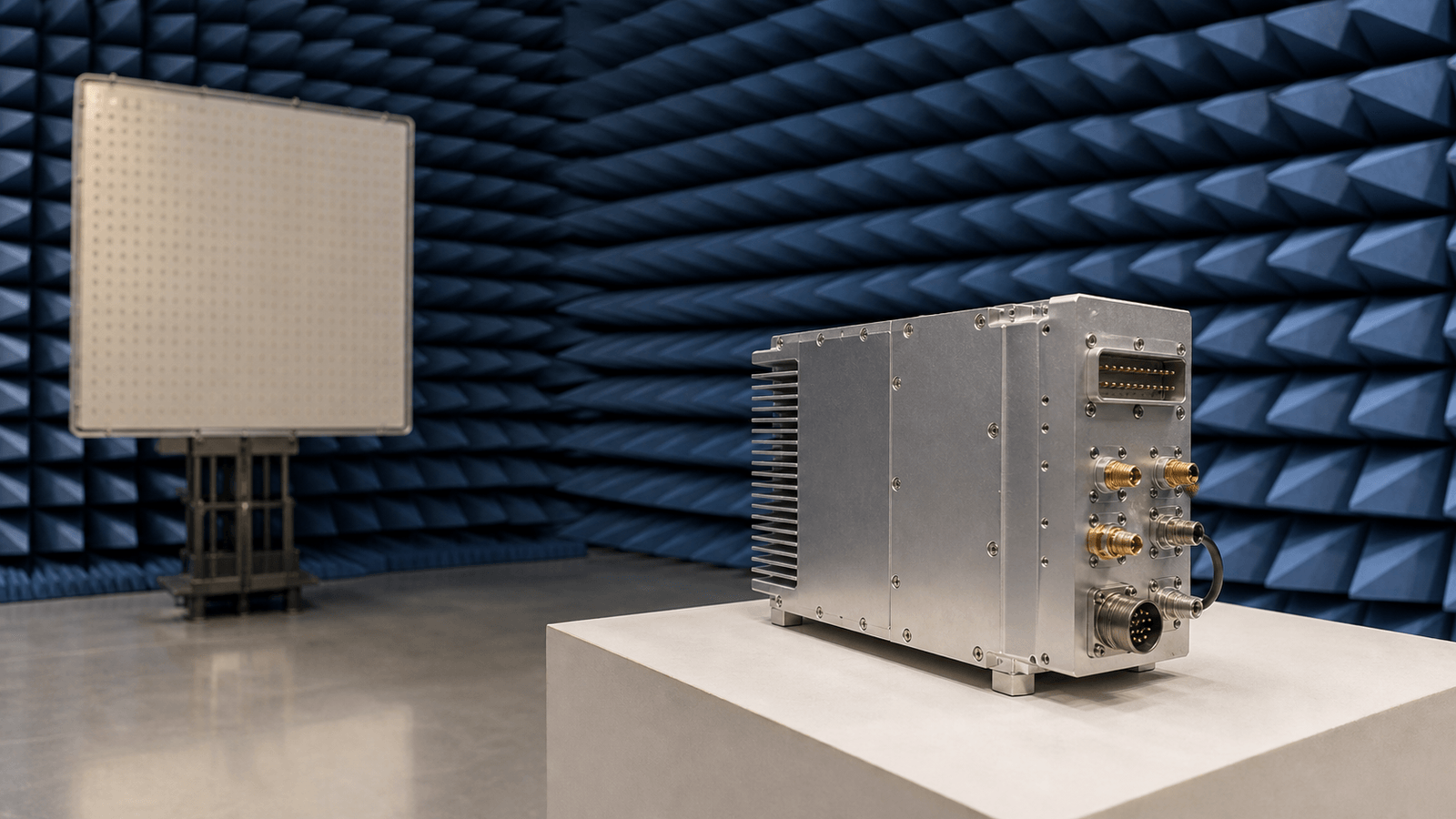
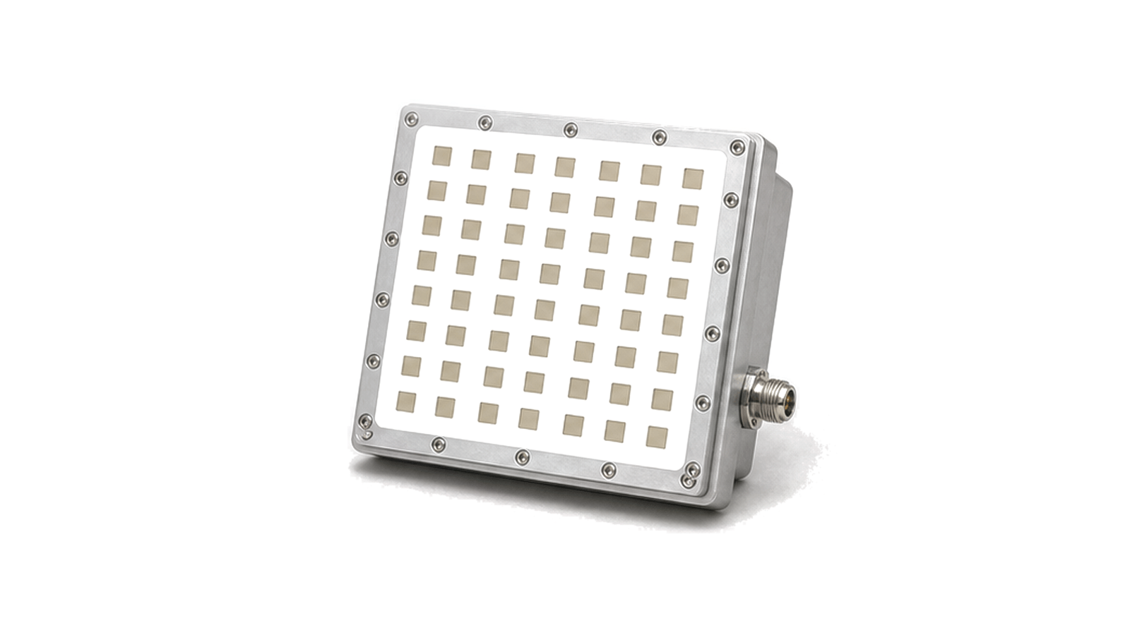
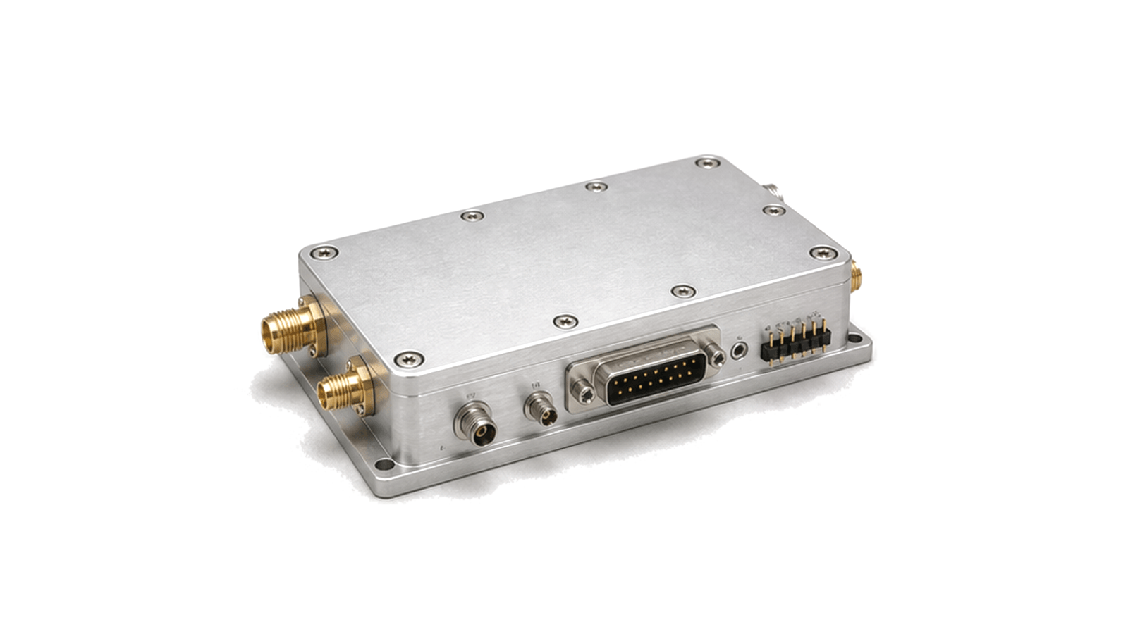
RF sensing and imaging systems use RF or microwave energy to detect or locate objects, surfaces and movement. Hardware paths may combine transmit excitation, antenna interfaces, protected low-noise reception, IQ conversion, RF detection and receiver modules.

RF Sensing & Imaging RF application visual

RF hardware for sensing and imaging paths

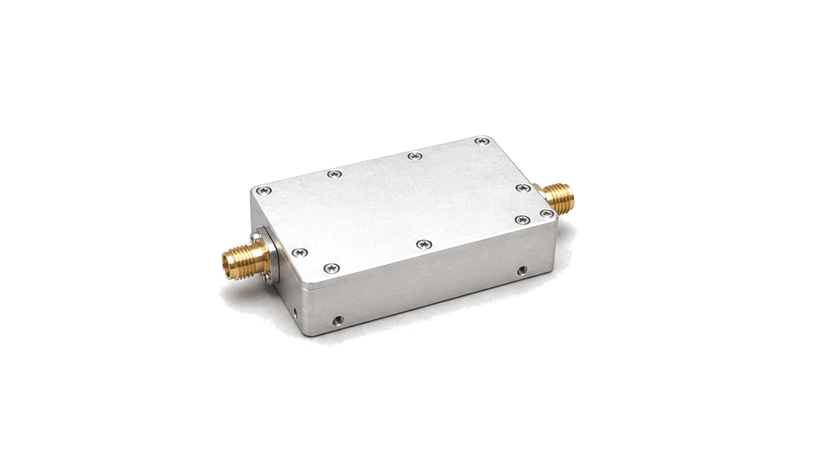
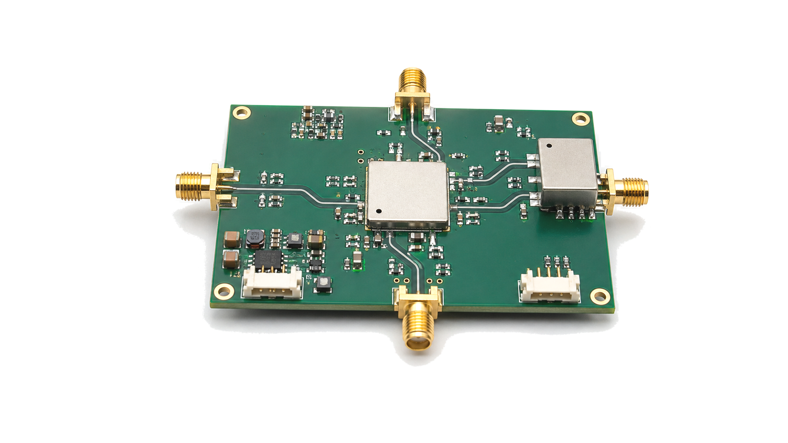
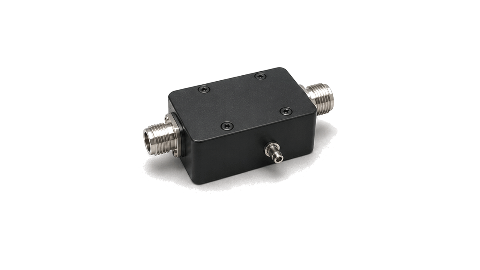
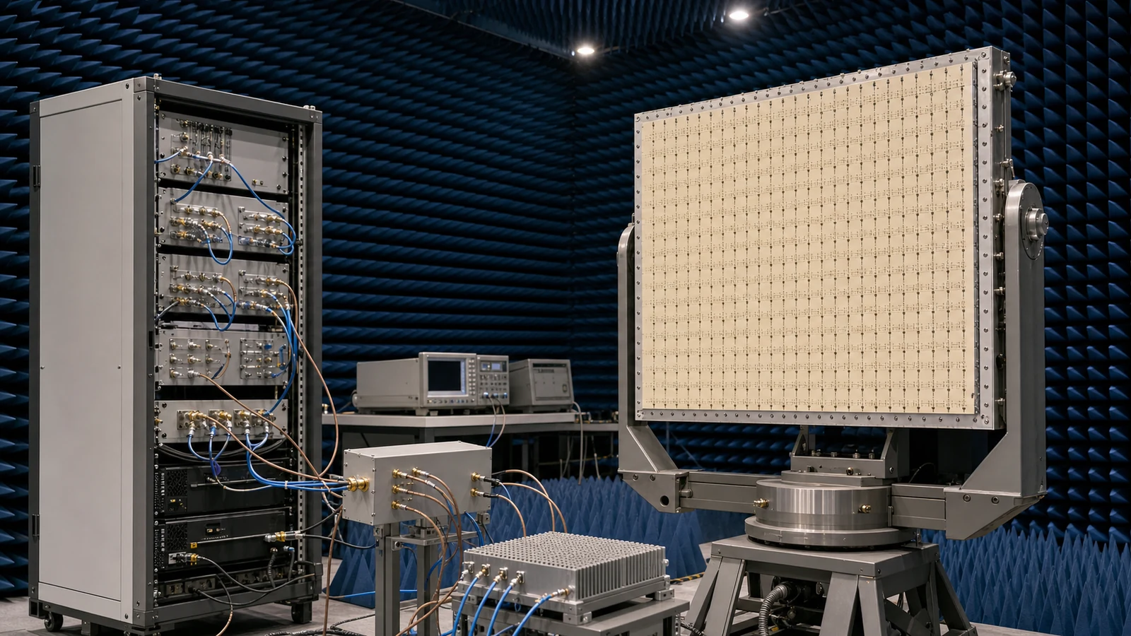
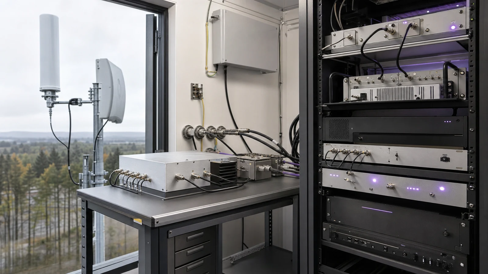
RF sensing and imaging systems use controlled RF or microwave energy to detect, locate or observe objects, surfaces and movement. The hardware path can include a transmit source or exciter, antenna interface, protected low-noise receiver chain, IQ conversion, RF detection and receiver modules that feed downstream measurement or processing equipment.

System context

Practical project boundaries include operating band, waveform format, receive sensitivity, dynamic range, timing stability, antenna aperture, overload protection, calibration method and the interface to the processing stage. These conditions shape the RF path without turning the application into a single product family.
Articles

FAQ

What must a radar Tx/Rx protection requirement include beyond receiver survival?

A complete Tx/Rx protection requirement includes survivable peak and average leakage, limiter and switch behavior, residual level, overload recovery, post-pulse gain/noise/phase and the nearest usable range gate.

What is the difference between antenna gain, directivity, beamwidth and sidelobes?

Directivity describes angular concentration, gain includes dissipative efficiency, beamwidth describes main-beam extent and sidelobes describe radiation outside that beam.

How do amplitude and phase errors affect a phased-array radar RF front end?

Channel amplitude and phase errors change coherent addition, beam direction, gain, sidelobes and null depth; their allowed distribution must be tied to the array pattern and calibration model.

How should the simultaneous signal environment be specified for a spectrum-monitoring receiver?

Define weak signals and every simultaneous strong emitter by frequency, waveform, bandwidth, level, duty cycle, timing, antenna or conducted coupling plane and required observation outcome.

Engineering inquiry

Share your RF requirement

Share the product, operating requirements and project context. Our engineering team will route your request to the right specialist.

AttachmentsAttach drawings, BOMs, specifications or test files. Up to 5 files, 10 MB each and 25 MB total.
or drag and dropPDF, DOCX, XLSX, CSV, TXT, JPG, PNG, S1P and S2P
Typically reviewed within one business dayProject information is handled confidentially