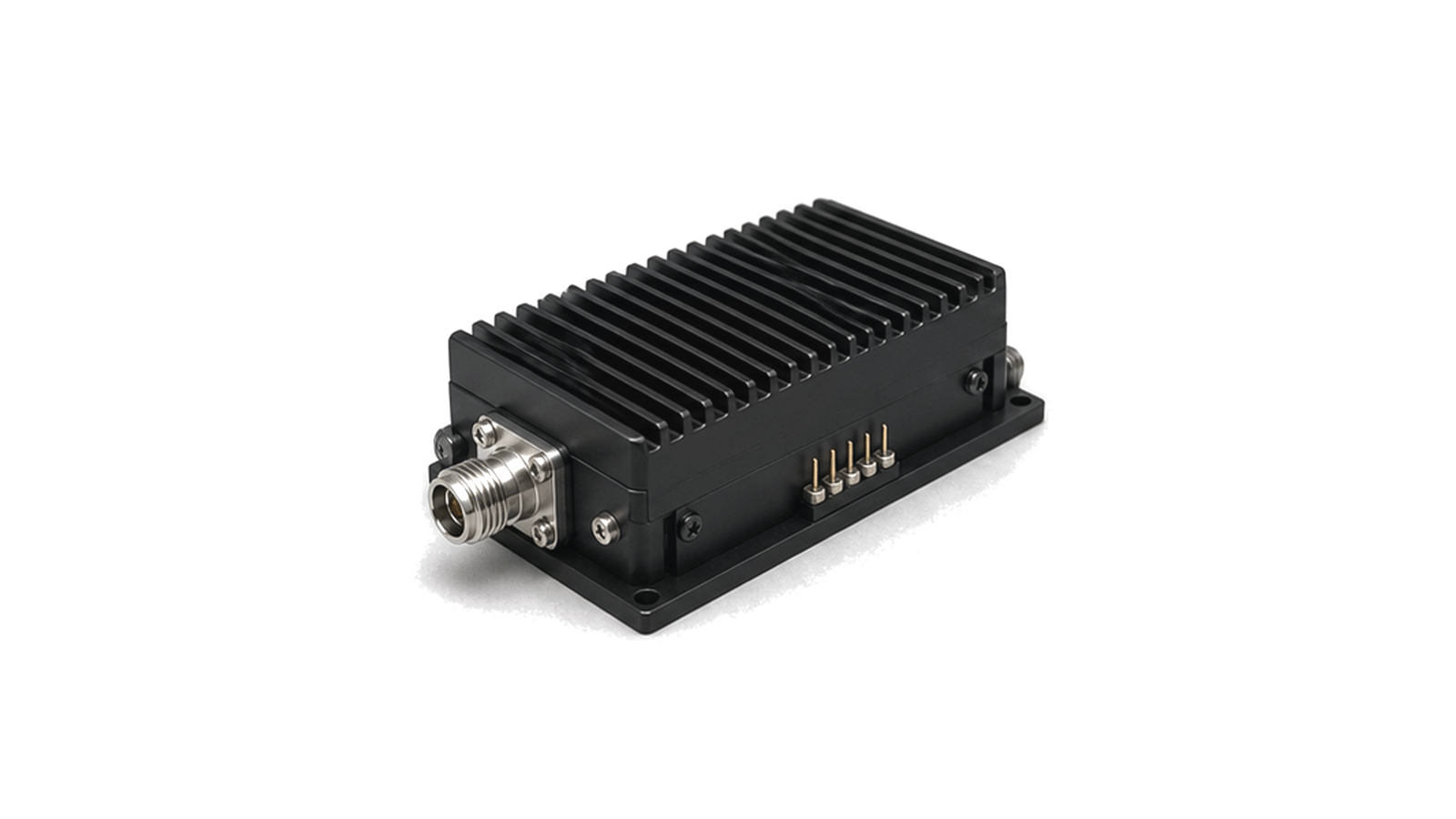
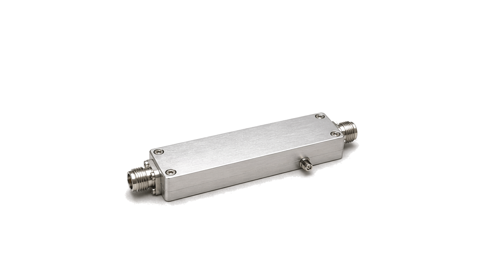
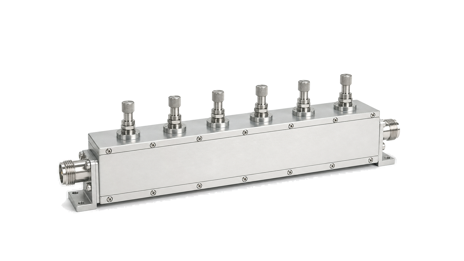
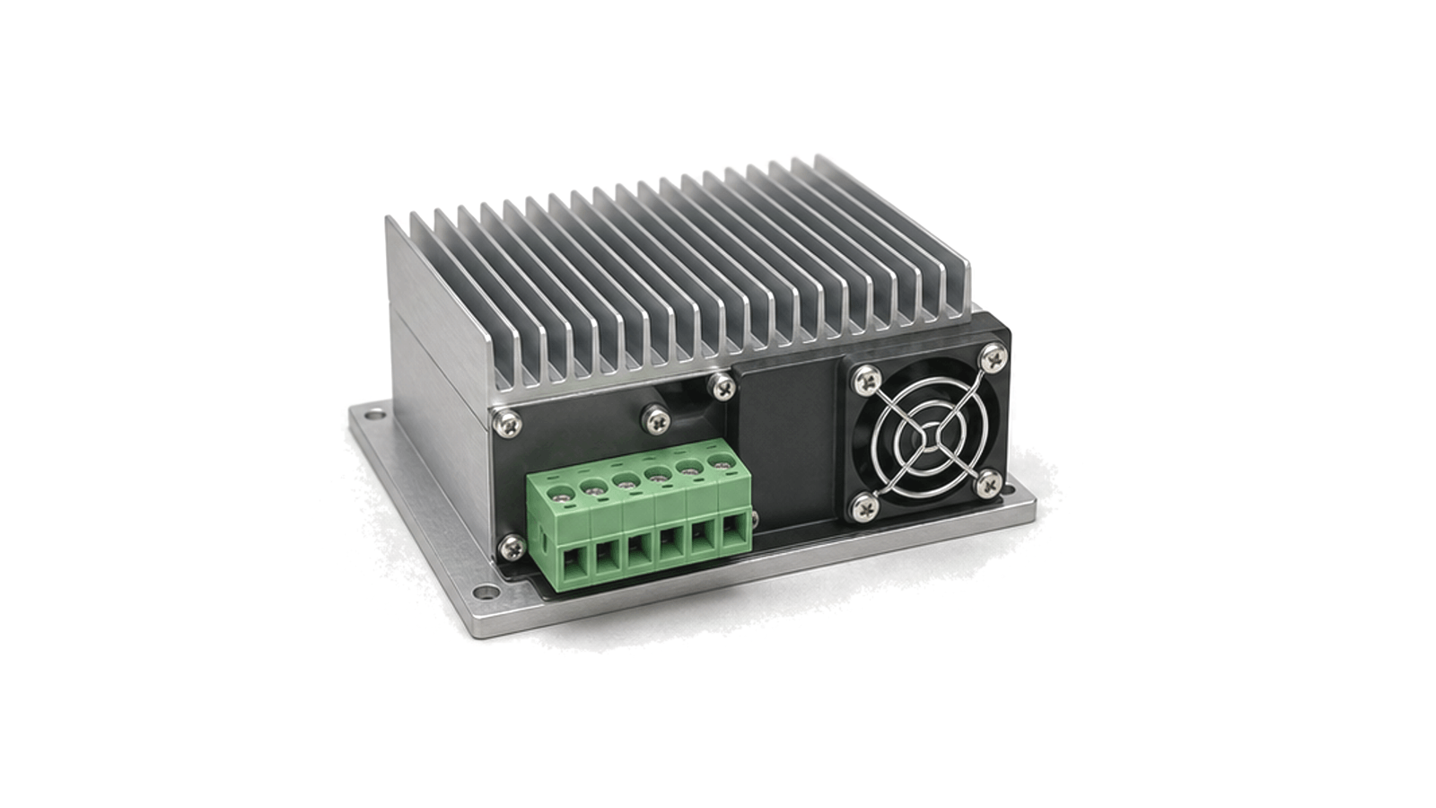
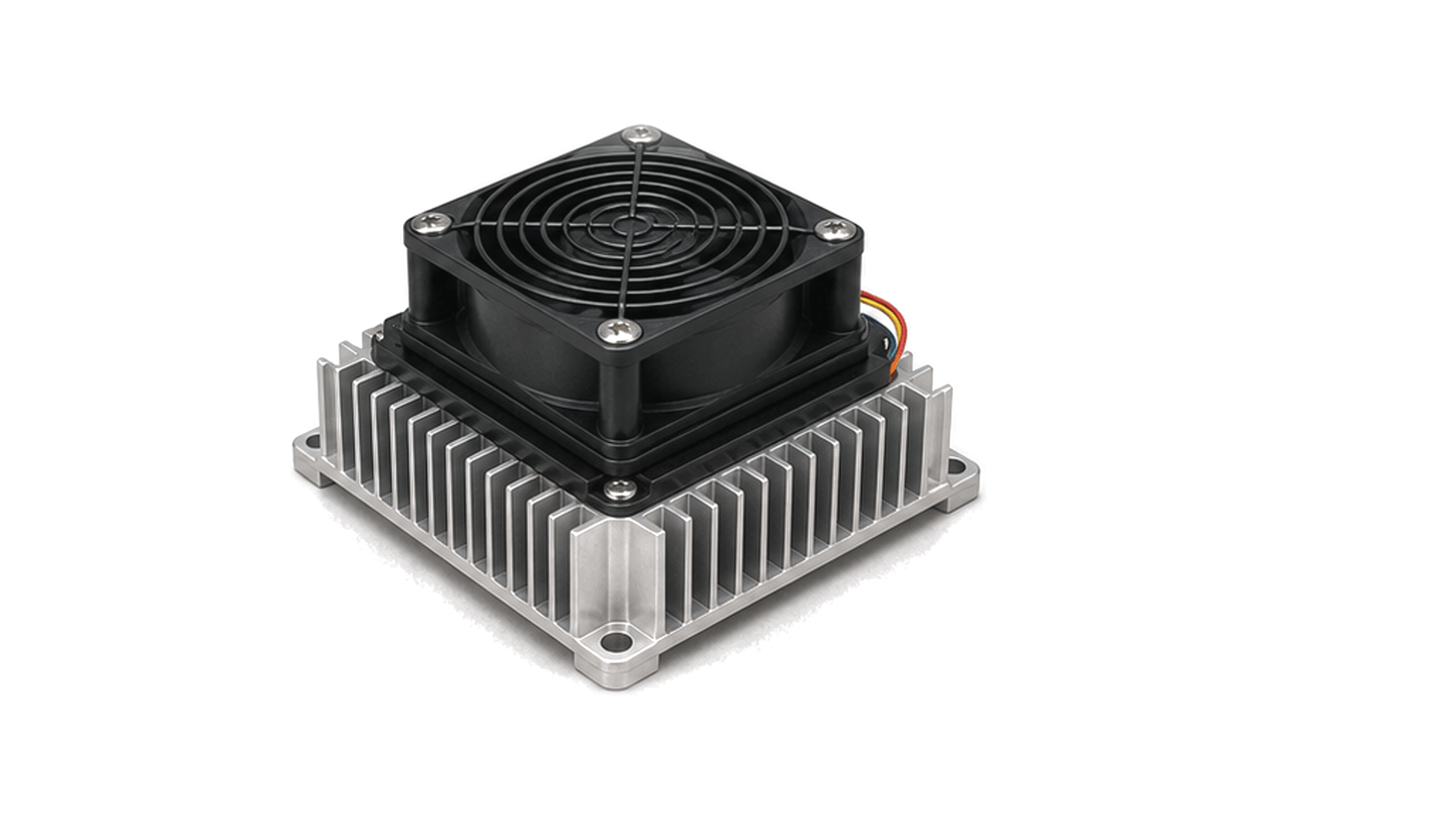
Transmit output path
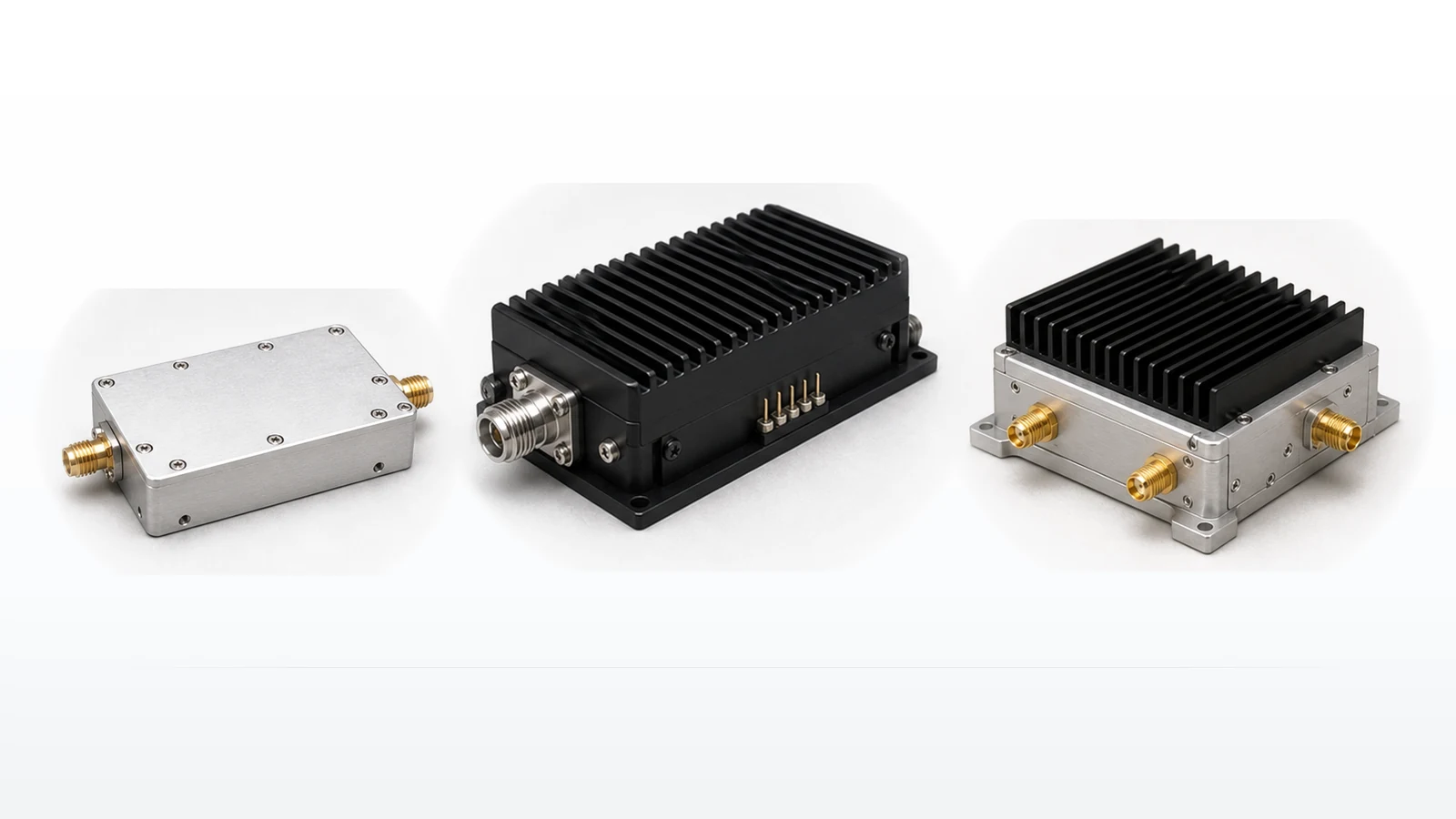
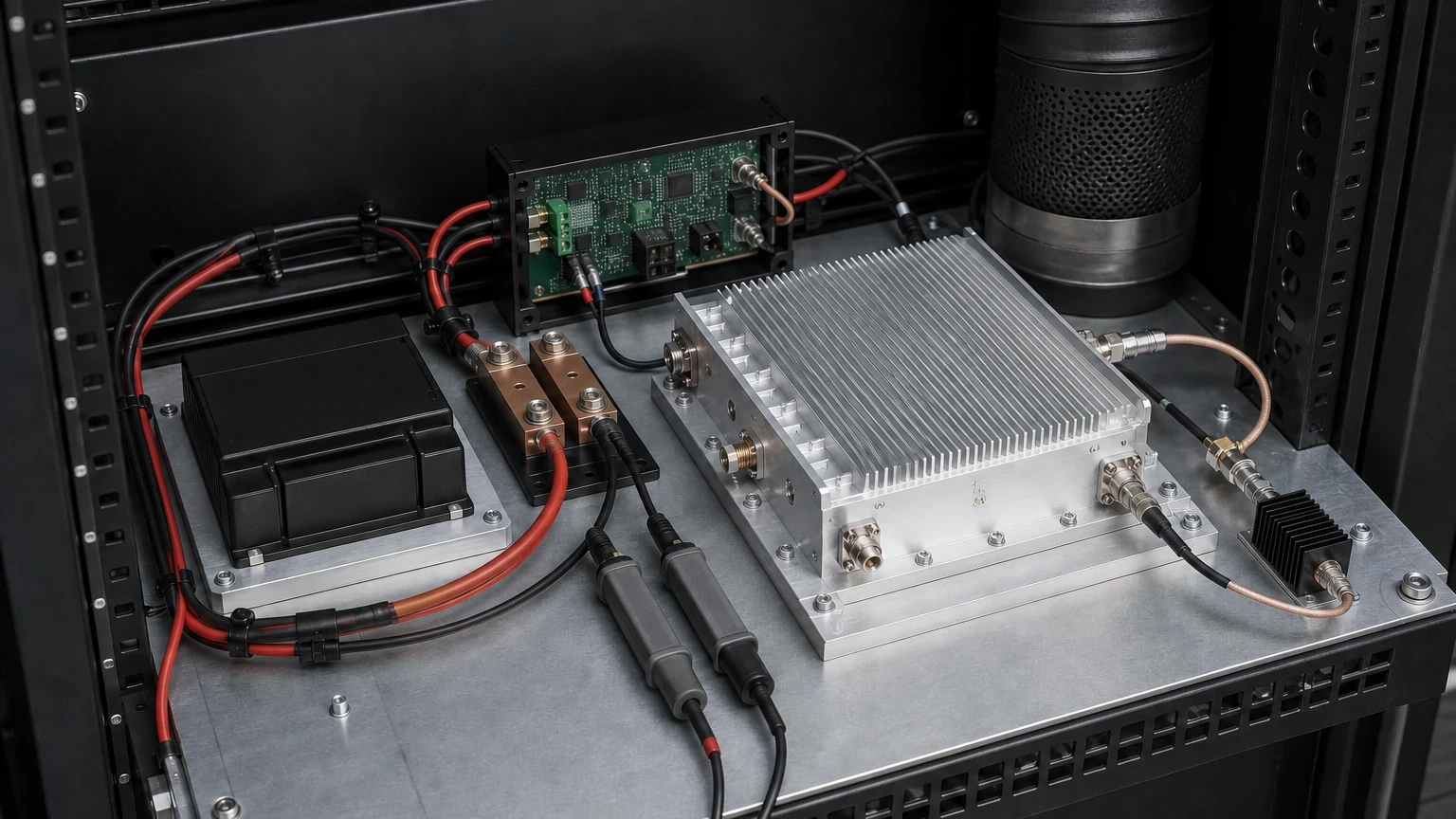
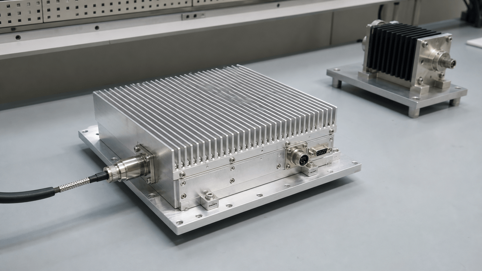
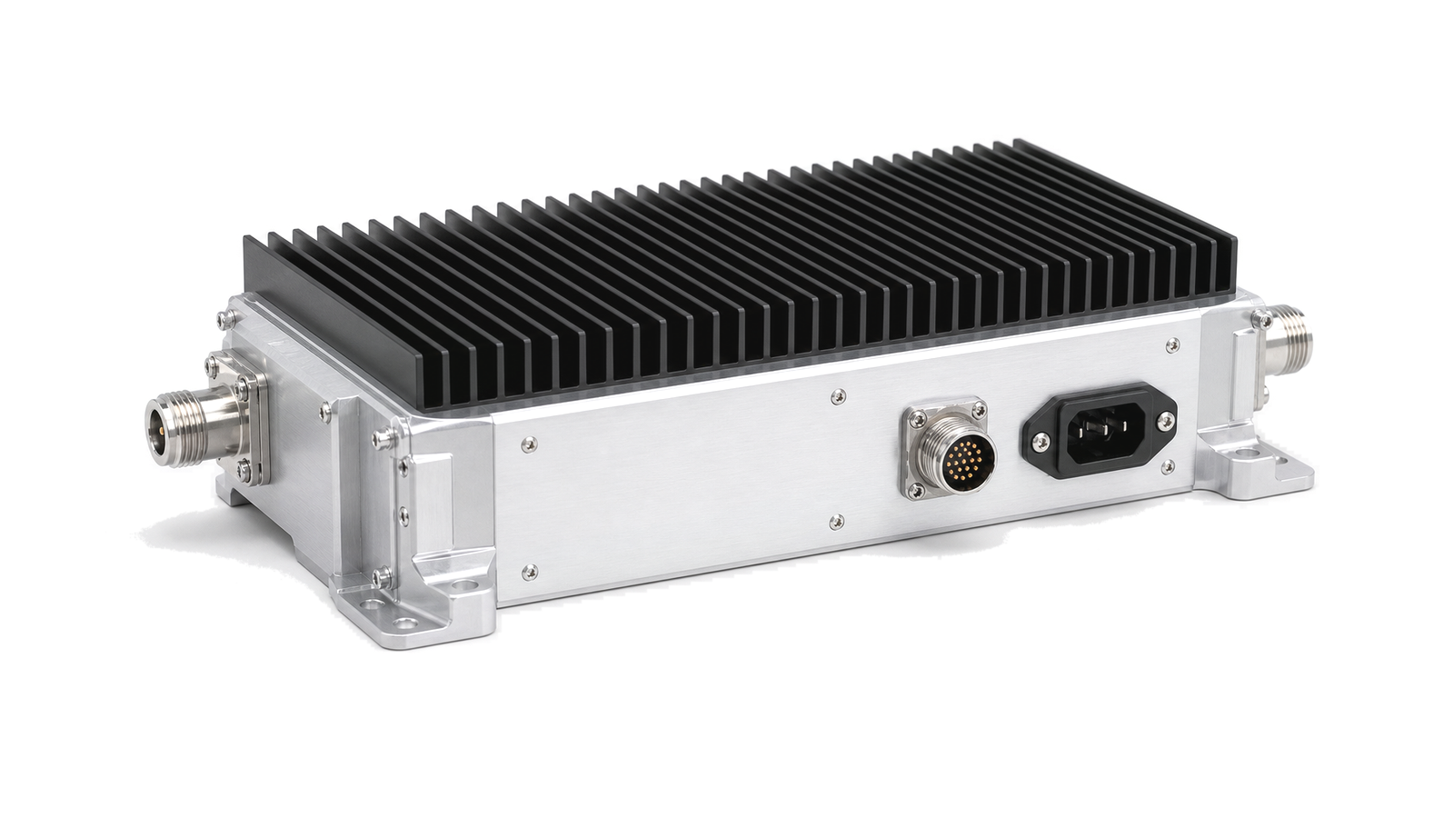
A transmitter power amplifier chain converts a stable RF or microwave drive signal into the power level needed at the antenna, load or test interface. It may include driver gain, one or more PA stages, output filtering, directional coupling, bias supply, monitoring and thermal control.
Chain role
The chain is used when the final RF output must be delivered as a controlled transmit path rather than as a single amplifier block. Power level, gain flatness, linear operating range, duty cycle, harmonic content, load mismatch behavior and heat removal are reviewed together.
Engineering inputs
Common inputs include drive level, saturated or linear output power, operating band, supply voltage, current margin, coupling points, protection behavior, cooling method, control interface, connector format and installation boundary.
A transmitter power-amplifier chain converts a controlled RF drive signal into the required load power without exceeding linearity, spectral-mask, thermal or mismatch limits. The chain is selected as a system: driver margin, final-stage gain, filtering, directional monitoring, bias sequencing, cooling and protection must be evaluated at the same operating conditions.
Architecture boundary
The chain begins at the specified RF drive reference plane and ends at the antenna, load or test-interface reference plane. It includes the driver, final PA, interstage and output matching, harmonic or band filtering, couplers, detectors, isolators or circulators when required, bias control and the thermal path. It does not include an unspecified upstream exciter or downstream antenna unless those interfaces are named in the acceptance plan.
Selection and integration inputs
- Define frequency range in MHz or GHz, modulation or pulse format, occupied bandwidth and required output in dBm or W at the final reference plane.
- State gain, gain flatness, P1dB or backed-off operating point, OIP3 or ACLR/EVM target, harmonic limits and acceptable noise contribution.
- Specify nominal 50 ohm interfaces, load VSWR, reflected-power duration, duty cycle, pulse width, crest factor and source-loss behavior.
- Record supply rails, sequencing, control logic, baseplate temperature, airflow or cold-plate conditions and allowable derating.
Acceptance evidence
- Calibrate cables, adapters and couplers to the named reference planes, then record small-signal gain and input/output match over the full band.
- Verify rated or backed-off output, spectral performance and efficiency at the stated waveform, temperature and duty cycle.
- Exercise startup, shutdown, overtemperature, overcurrent and representative mismatch states; record alarms, recovery and any permanent derating.
Information required for an RFQ
Provide the frequency plan, waveform, drive level, required output, linearity or spectral limit, average and peak power, duty cycle, load VSWR, thermal boundary, supply and control interfaces, environmental range and the acceptance reference planes. A headline wattage without these conditions is not sufficient to select or compare a PA chain.