A reproducible result begins before the first sweep
Freeze the DUT state and the measurement boundaries before selecting the instrument menu. Record bias, control state, waveform, frequency, input level, load, temperature and stabilization time. Name the calibration and DUT reference planes, identify every cable, adapter and fixture that remains inside the reported value, and assign a receiver range, uncertainty term and retained record to each claimed parameter. A measurement is not comparable merely because both files contain a value called gain, P1dB or return loss.
Define the evidence chain for every parameter
| Claim | State and stimulus | Boundary and correction | Minimum retained evidence |
|---|---|---|---|
| S-parameters | Bias, small-signal level, frequency grid, temperature | VNA calibration plane; fixture included or de-embedded | Complex data, calibration method, verification check and port power |
| Gain or conversion | Input level, LO and gain state, load, bandwidth | Input/output planes with cable and fixture loss treatment | Raw input/output levels, correction files and uncertainty |
| P1dB | Single-tone sweep, dwell, bias and thermal state | Power at named DUT planes; receiver remains linear | Unsaturated gain fit, full sweep and compression criterion |
| IMD | Two tones, per-tone power, spacing and phase behavior | Source IMD and receiver distortion below the DUT products | Fundamental and product traces, residual-system check |
| Pulsed or modulated result | Pulse timing or waveform file, duty, crest factor and trigger | Calibrated waveform at the DUT plane and stated analysis window | Waveform identity, timing, bandwidth, averaging and receiver settings |
Write a DUT state sheet that another lab can reproduce
The state sheet is the control document for the measurement. Include serial number or sample identity, hardware revision, firmware, connector orientation, bias sequence, rail values at the DUT, quiescent current, control words, gain or attenuation state, warm-up or soak time, case or baseplate temperature, airflow or cold-plate condition, load VSWR, grounding and any protection state. For converters, include LO frequency and power at the DUT plane. For pulsed devices, include pulse width, PRF, duty cycle, gate timing and measurement aperture.
Do not hide state changes inside instrument automation. If compression increases current, a protection loop changes gain, or temperature drifts during a power sweep, record those channels with the RF trace. Otherwise the curve cannot distinguish device behavior from state movement.
Name the calibration plane and the reporting plane separately
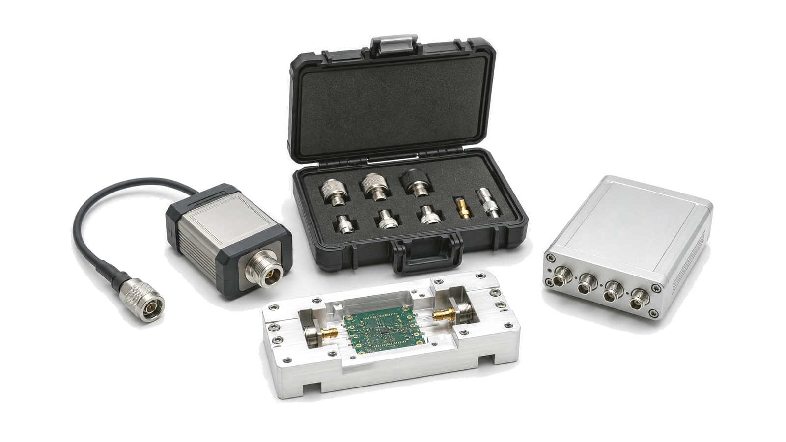
The calibration plane is where systematic correction is established; the reporting plane is where the project claims the result applies. They may coincide at coaxial DUT connectors, but a probe station, evaluation fixture, bias tee, switch matrix, cable harness or waveguide transition can place the DUT behind additional networks. State whether those networks are included, characterized and de-embedded, or accepted as part of the measured assembly.
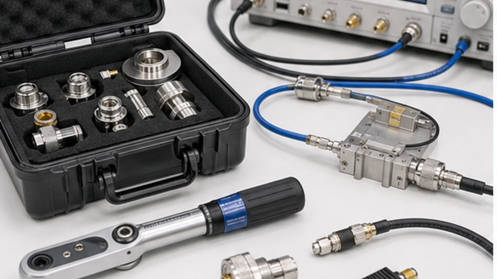
Move a reference plane only with a defensible network model or measurement. Preserve fixture S-parameters, orientation, port mapping, connector type, torque, temperature and date. Do not de-embed a nonlinear, unstable or poorly repeatable fixture as if it were an ideal two-port. Verify the corrected result with a known check device or a second method where the decision risk justifies it.
Worked compression and guard-band decision
An amplifier shows 20.0 dB small-signal gain at the named input and output planes. At an input of +5.0 dBm, measured output is +24.0 dBm, so gain is 19.0 dB: the measured output P1dB is +24.0 dBm under that bias, frequency, dwell and thermal state. If the procurement minimum is +23.5 dBm and the agreed expanded measurement uncertainty is 0.4 dB, a conservative acceptance rule may require at least +23.9 dBm for an unambiguous pass. That 0.4 dB is not a universal guard band; the buyer and supplier must agree the decision rule, uncertainty coverage and treatment of borderline units.

Keep small-signal measurements inside their linear boundary
Set VNA port power low enough that the DUT, receiver and any active fixture remain linear, yet high enough for usable dynamic range. For active devices, verify actual power at the DUT plane and monitor reverse or leaked power where it can compress a receiver. Record IF bandwidth, averaging, frequency spacing and smoothing. Smoothing may improve presentation but cannot replace raw complex data or an uncertainty estimate.
Measure the S-parameters needed by the decision: input/output match, forward/reverse transmission, isolation and phase. Derived stability, transducer gain or mismatch-corrected power inherits the uncertainty and correlation of the measured data. Cable flexure, connector repeatability, noise, drift and receiver nonlinearity can move corrected results, so a fresh calibration alone does not close the error budget.
Measure gain, noise and conversion with compatible planes
Gain is a ratio only after input and output quantities use compatible bandwidth, impedance, detector behavior and reference planes. For a frequency converter, identify the RF, LO and IF frequencies, wanted sideband, spectrum inversion, gain state and filters included in the result. For noise figure, state source calibration, input loss correction, gain state, receiver noise contribution and whether mismatch correction is applied.
When comparing candidates, do not place a bare device result beside a filtered, amplified module result without normalizing included functions. If cable loss is removed at input but retained at output, the reported gain will be internally inconsistent even when each instrument reading is individually traceable.
Separate compression, harmonics and intermodulation tests
P1dB uses a single-tone power sweep and a stated small-signal reference fit. Define whether the reported point is input or output referred, how gain is fitted, sweep direction, dwell and thermal control. Harmonic testing uses the same fundamental but requires calibrated receiver coverage at each harmonic and enough preselection to prevent analyzer-generated products.
Two-tone IMD requires tone spacing, per-tone power, combined power convention, source isolation and receiver headroom. Measure the residual system with the DUT replaced by a suitable through or attenuator. The third-order products may indicate near-tone nonlinear behavior, but neither IP3 extrapolation nor P1dB alone predicts modulated EVM, spectral regrowth or memory effects. Use the actual waveform when those are the acceptance quantities.
Treat pulsed and modulated operation as different DUT states
A pulsed device can show different bias settling, droop, thermal memory and compression from CW operation. Calibrate peak or time-gated power at the DUT plane, state the trigger and observation window, and capture rise, fall, overshoot and within-pulse behavior. For burst operation, include burst length and idle interval.
For modulated signals, retain the waveform identity, sample rate, occupied bandwidth, crest-factor statistics, digital scaling and any predistortion. Verify that source and receiver contributions are below the DUT error or are included in the uncertainty. A clean generator display at one reference plane does not prove that the waveform remains calibrated after cables, converters and fixtures.
Build uncertainty around the decision, not around the instrument brochure
List systematic corrections and residual terms at the reported plane: calibration-standard definition, source and receiver level accuracy, mismatch, directivity, tracking, noise, drift, cable movement, connector repeatability, fixture model, receiver linearity, temperature and repeatability. Include correlation when the same calibration or receiver contributes to several derived quantities. State whether uncertainty is standard or expanded and name the coverage factor or method.
Use uncertainty to write the acceptance rule before testing units. A guard band can reduce false acceptance, but it also creates an indeterminate or rejected region. The rule must match project risk and contract language. Do not subtract a convenient margin from every specification without tracing which uncertainty terms actually apply.
Separate design characterization from production acceptance
| Full characterization | Production acceptance | Correlation requirement |
|---|---|---|
| Dense frequency, power, state and temperature coverage | Reduced points selected for fault detection and process control | Acceptance points must detect the failure modes seen in characterization |
| Detailed uncertainty and diagnostic traces | Controlled fixture, limits and periodic verification | Fixture and reference-unit drift must be bounded |
| Representative samples and engineering investigation | Every unit or defined sampling plan | Sample coverage and escape risk are documented |
| May include destructive or long-duration corners | Cycle time and DUT safety are constrained | Reduced stress has a justified relationship to qualification evidence |
Production acceptance is not a shortened copy chosen only for speed. It is a correlated detection plan. Track golden or check standards, fixture wear, cable replacement, calibration interval, software revision and control-chart behavior so a stable table of pass values is not mistaken for a stable measurement process.
A practical characterization sequence
- Freeze DUT states and project decisions. Separate typical exploration from guaranteed acceptance claims.
- Draw the physical and mathematical reference planes. Mark every cable, adapter, fixture, probe, bias network and correction.
- Verify the empty system. Check source residuals, receiver linearity, dynamic range, leakage and repeatability before inserting the DUT.
- Run small-signal measurements first. Establish match, transmission, isolation and stable operating states.
- Add gain, noise or conversion tests. Keep planes and included functions consistent.
- Run power-dependent tests separately. Capture current, temperature and protection state with P1dB, harmonics and IMD.
- Repeat the states that create risk. Cover band edges, gain states, temperature, waveform, load and supply corners.
- Estimate uncertainty and apply the agreed decision rule. Retain borderline results instead of rounding them into a pass.
- Correlate the production screen. Prove it catches known weak modes and remains stable between calibrations.
Retain enough information to reproduce and challenge the result
The data package should contain raw traces, processed values, formulas, limit tables, uncertainty statement, calibration identity and time, instrument model/serial/firmware, correction files, fixture identity and S-parameters, cable and adapter list, automation revision, DUT state sheet, environmental log, operator or station identity and deviations. Use machine-readable files for traces and metadata; a screenshot is supporting context, not the primary measurement record.
Common test-plan failures
- Reporting connector-plane limits while the calibration stops before an uncharacterized fixture.
- Using a fresh calibration as a substitute for cable-flexure, drift, mismatch and receiver-linearity analysis.
- Measuring P1dB after the DUT has heated differently from its specified operating mode.
- Quoting two-tone IP3 without tone spacing, per-tone power and residual-system IMD.
- Applying CW data to pulsed or high-crest-factor operation without equivalence evidence.
- Removing fixture loss but not fixture mismatch or uncertainty.
- Defining production limits before the reduced test is correlated to full characterization.
- Saving screenshots while discarding complex traces, calibration state and automation settings.
Minimum characterization and RFQ information
- DUT revision, quantity, operating modes, bias sequence and protection behavior
- Frequency bands, port impedance, connector or fixture interfaces and reporting planes
- CW, pulsed or modulated waveform conditions and required bandwidth
- Small-signal power, S-parameters, gain, phase, noise and isolation claims
- P1dB, harmonics, IMD, EVM or spectral-regrowth methods and criteria
- Temperature, supply, load mismatch, gain state and stabilization conditions
- Calibration method, standards, fixture/de-embedding responsibility and check device
- Uncertainty statement, coverage and acceptance decision rule
- Characterization matrix versus per-unit production screen
- Raw-data format, metadata, traceability, retention and report language