Build one traceable requirement and evidence chain
A defensible RF hardware specification says what the item must do, where each limit applies, which conditions it must survive and perform through, how every requirement will be verified, and which exact configuration the evidence represents. The work starts with a mission and life-cycle profile, not a list of standards. RF, DC, data, timing, mechanical and thermal interfaces are frozen together; environmental and assurance requirements are then tailored to that boundary, and qualification, acceptance and change-control records close the loop.
Define the mission profile, item boundary and assurance decision
Name the item being procured: component, converter, amplifier, line-replaceable unit, payload electronics assembly, ground-support unit or installed subsystem. State the platform, mission phase, service life, storage and transport interval, maintainability concept, consequence of failure and any authority that approves tailoring. The same RF module can face very different requirements when it is replaceable ground equipment, an airborne unit or inaccessible flight hardware.
List nominal, standby, calibration, degraded, safe, startup, shutdown and credible fault modes along a time line. For each mode record active RF paths, waveform, duty cycle, simultaneous channels, supply state, thermal boundary and required response. Separate survival from operation and operation from retained performance. Terms such as rugged, mission ready or space grade are not measurable requirements and must not be used as substitutes for the item boundary and mission state.
Freeze every interface and allocate RF performance at named planes
Create an interface control set for RF ports, DC input, enable and protection, telemetry, data, timing and reference signals, grounding and bonding, connectors, harnesses, cooling and mounting datums. For every RF port define continuous bands, forbidden gaps, impedance, waveform, peak and average power, gain or loss, noise, linearity, phase, group delay, spectral products, mismatch, switching state and simultaneous operation at a named connector or waveguide plane. An internal module result cannot be treated as installed performance when cable, filter, antenna or harness effects are outside the test plane.
Close minimum and maximum budgets across tolerance, temperature, aging, radiation where applicable, supply variation and mode changes. Include source phase noise, converter spurs, filter rejection, amplifier compression and heat, receiver noise and blockers, antenna or load mismatch and calibration paths according to the chain. Define DC steady range, inrush, transients, hold-up, sequencing and fault energy as interfaces rather than vague platform conditions. The requirement matrix should show which item owns each margin and which measurement proves it.
Derive environmental, EMC and thermal conditions from the real life cycle
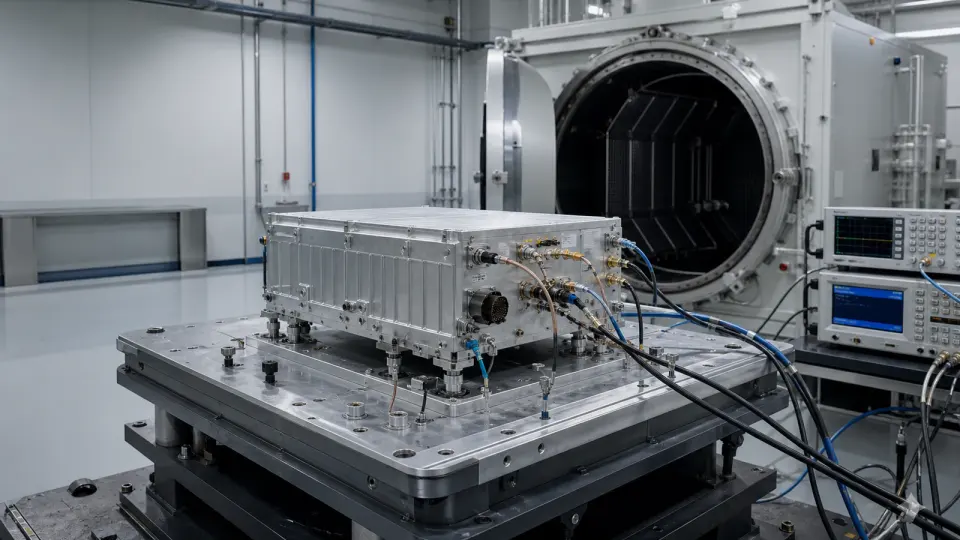
Map storage, handling, transport, launch, flight, vehicle, shipboard, outdoor, ground-station or orbital exposure before selecting tests. Tailor temperature, thermal cycling, altitude or vacuum, humidity, salt, sand, dust, rain, shock, vibration, acoustics, acceleration, contamination and radiation only where the profile supports them. Specify axes, levels, spectra, rates, duration, dwell, operating state, monitoring, margin and pass criteria. MIL-STD-810 or GEVS supplies methods and planning guidance; neither creates a universal certification by appearing on a drawing.
Define conducted and radiated emissions and susceptibility at the correct equipment boundary with the intended enclosure, power source, cables, loads, bonding and operating modes. For space hardware, derive radiation assurance from the mission environment and component susceptibility instead of claiming generic radiation hardness. Join the electrical test to thermal reality: state baseplate, airflow or coolant conditions, dissipated power, transient duty, junction or case limit and sensor correlation. Functional RF measurements before, during when required, and after exposure reveal degradation that a survival inspection can miss.
Turn parts and materials assurance into controlled procurement data
Choose the applicable component assurance class, screening, qualification, derating and radiation controls from project risk, mission life, repairability and approved standards. Record manufacturer and authorized supply source, exact part number and revision, lot and date code, country or facility constraints where contractually required, certificate and test-data needs, storage, moisture or ESD control and counterfeit-avoidance process. Commercial, military and space-grade labels do not replace a reviewed parts plan.
Control materials, finishes, adhesives, cables, connectors, soldering, cleaning, outgassing or contamination-sensitive processes, torque, bonding and workmanship at the assembly level. Preserve approved deviations and nonconformances. Screening cannot turn an unsuitable design into an assured part, and a higher component class cannot compensate for excessive electrical, thermal or RF stress. Derating analysis must use the actual circuit state and worst credible environment, then remain linked to the BOM and drawing revision that was verified.
Plan verification method, article pedigree and evidence before ordering hardware
Give every shall requirement a unique source, verification method, level, article, configuration, facility, condition, margin and pass criterion. Use test where behavior must be observed, analysis where validated models and inputs are adequate, inspection for physical or documentary attributes and demonstration only when a controlled functional showing is sufficient. Distinguish breadboard, engineering, qualification, protoflight, acceptance and service articles; evidence from one pedigree is not automatically transferable to another.
Sequence baseline RF characterization, functional and interface tests, EMC, environmental exposure and final end-to-end verification so latent damage and configuration drift can be found. Record fixtures, adapters, cable corrections, uncertainty, calibration status, software, limits and raw results. Define similarity rules when several configurations exist and state what changes require partial or full re-verification. A report that contains only pass labels cannot support future production, failure review or substitution decisions.
Keep configuration, obsolescence and delivery evidence under one change process
The delivered identity includes serial number, hardware drawing, schematic, BOM, approved manufacturers, lot and date codes, firmware or programmable-device image, calibration coefficients, manufacturing traveler, test procedure and results, deviations, waivers and nonconformance disposition. Baseline these records before qualification and acceptance. A replacement unit is equivalent only when the changed configuration has a documented impact assessment and the required verification has been repeated or validly inherited.
Manage diminishing sources and material shortages throughout the life cycle. Monitor lifecycle notices and supply risk, define notification periods and data rights, assess stock, redesign, alternate sources and technology refresh before a shortage becomes urgent. An alternate with the same package and headline RF figures may change phase noise, spurs, thermal resistance, radiation response, EMI or firmware behavior. Delivery should include a controlled data index, open actions, calibration and shelf-life status, and named triggers for requalification, not merely a certificate of conformance.
| Decision boundary | Requirement to freeze | Reject the proposal when |
|---|---|---|
| Mission and item | Platform, life-cycle phases, modes, service life, failure consequence and exact item boundary | Rugged or mission ready replaces measurable states |
| Interfaces | RF planes, DC, data, timing, control, harness, grounding, cooling, mounting and ownership | A connector list has no limits, states or datums |
| RF performance | Bands, waveform, power, gain, noise, linearity, phase, spurs, mismatch and margins by mode | Typical room-temperature data represents the installed chain |
| Environment and EMC | Tailored stress, axes, duration, state, monitoring, margin, emissions, susceptibility and pass criteria | A standard number is presented as a generic certification |
| Parts and materials | Class, screening, qualification, derating, source, lot, process and deviation controls | Grade labels replace a parts and materials plan |
| Verification | Requirement ID, method, level, article pedigree, facility, condition, uncertainty and raw evidence | Qualification and acceptance are used interchangeably |
| Configuration and change | Serial, BOM, drawings, firmware, calibration, waivers, similarity and re-test triggers | Substitutions are approved from form, fit and function alone |
| Lifecycle delivery | DMSMS process, notices, data index, open actions, shelf life, calibration and support boundary | Only a certificate and summary report are delivered |
Worked decision: a bench-compliant RF module can fail after platform integration
Consider a telemetry upconverter and power-amplifier assembly that meets gain, output power and spurious limits on a room-temperature bench. In the installed platform, a long 28 V harness creates startup droop, the chassis interface raises baseplate temperature, a nearby transmitter drives an untested simultaneous-signal state, and vibration changes a coax connector. A defensible requirement freezes the power transient at the module terminals, thermal interface and duty cycle, RF reference planes, blocker state, cable configuration, vibration axes and operating mode. The verification sequence records baseline RF data, monitors the unit during tailored exposure where required, repeats end-to-end RF tests afterward and ties the result to serial, BOM, firmware and cable revisions. The original bench result remains useful, but it is not installed qualification evidence.

Build the verification flow before the first qualification article
- Approve the mission profile, item boundary, modes, service life, failure consequence and tailoring authority.
- Freeze RF, DC, control, data, timing, grounding, harness, mechanical and thermal interface documents.
- Allocate minimum and maximum RF, power and heat budgets at named reference planes for every relevant mode.
- Create the life-cycle environmental profile and tailor stress, axes, duration, operating state and pass criteria.
- Approve component, material, process, derating, radiation where applicable, source and traceability plans.
- Map every requirement to test, analysis, inspection or demonstration, product level and article pedigree.
- Baseline the article serial, BOM, drawings, firmware, calibration, fixtures, procedures and facility configuration.
- Run interface and RF baselines, required EMC and environmental verification, then repeat end-to-end performance.
- Resolve anomalies, deviations and waivers through configuration control and repeat affected verification.
- Deliver raw data, uncertainty, logs, certificates, configuration index, open actions and re-verification triggers.
Failures hidden by an aerospace-grade label
- Copying a generic standard list without a life-cycle profile or tailoring record
- Leaving the equipment boundary unclear between internal module, enclosure, harness and platform
- Using typical RF data without temperature, mode, tolerance, aging or reference planes
- Verifying survival while omitting RF performance during or after the stress
- Applying an equipment-level EMI standard directly to an internal module or whole platform
- Claiming radiation hardness without mission environment, device response and assurance evidence
- Treating screening, grade or certificate of conformance as a complete parts plan
- Reusing qualification data from a different BOM, firmware, cable or thermal configuration
- Approving an alternate part from package and headline specifications without impact analysis
- Delivering summary reports without raw data, uncertainty, serial identity and change history
Information required for an aerospace, defense or space RF hardware RFQ
- Platform, mission, item boundary, installation level, service life and repair or replacement concept
- Nominal, standby, calibration, degraded, safe, startup, shutdown and fault modes
- Frequency ranges, waveforms, bandwidth, simultaneous channels, duty cycle and timing behavior
- RF reference planes, impedance, power, gain or loss, noise, linearity, phase, spurs and mismatch limits
- DC range, inrush, transients, sequencing, protections, controls, telemetry, data and reference interfaces
- Connector, harness, grounding, bonding, envelope, mass, mounting, torque and thermal-interface drawings
- Storage, transport, handling and operational temperature, pressure, humidity, contamination and ingress
- Vibration, shock, acoustics, acceleration, salt, sand, rain, vacuum or radiation profiles where applicable
- Conducted and radiated emissions and susceptibility boundary, cable set, modes and pass criteria
- Component class, screening, qualification, derating, radiation, source, lot and counterfeit controls
- Materials, finishes, workmanship, cleanliness, ESD, moisture, shelf-life and process evidence
- Verification matrix, test-article pedigree, qualification and acceptance strategy, margins and uncertainty
- Serial, BOM, drawings, firmware, calibration, deviations, waivers, raw data and configuration index
- DMSMS monitoring, change notification, alternate-part approval, data rights, support and re-test triggers
Continue the aerospace RF engineering decision
- Review aerospace, defense and space RF applications
- Review avionics and telemetry RF applications
- Review space payload and ground-support RF paths
- Review electronic-warfare RF application boundaries
- Review rugged RF module qualification solutions
- Read the RF coaxial cable assembly specification guide
- Send the mission profile, interfaces, environment and evidence requirements