
LCRF

Privacy preferences

Choose optional purposes independently. You can change or withdraw your choice at any time from the footer.

Strictly necessary

Required for security, session functions and storing your privacy choice.

Always active
Preferences

Remembers optional display or language settings when these features are enabled.

Analytics

Uses first-party visitor and session identifiers to measure pages, referrals and inquiry interactions.

Marketing

Allows marketing measurement or third-party advertising technologies if they are introduced in the future.

Tactical Communications RF Chain

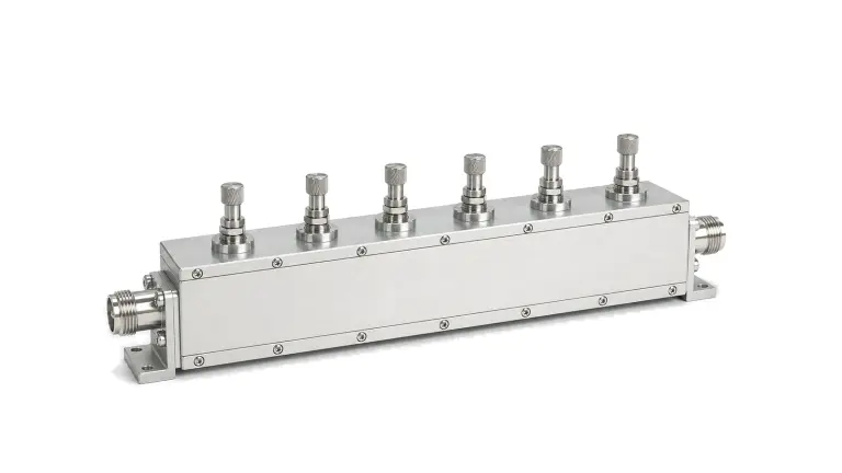
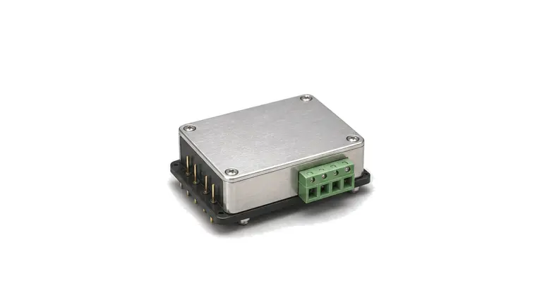
Tactical communications RF chains organize receiver and transmitter front ends, PA stages, switching, filtering, DC-DC power and antenna interconnect for mobile, vehicle-mounted and field communication equipment.

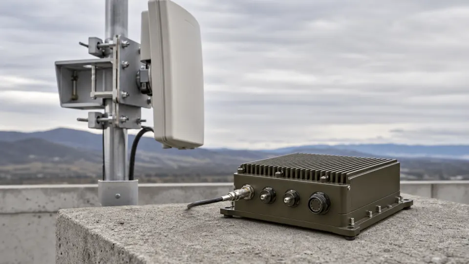
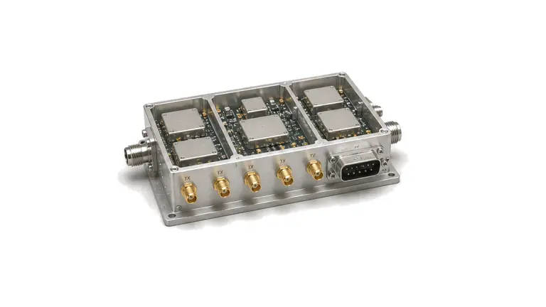
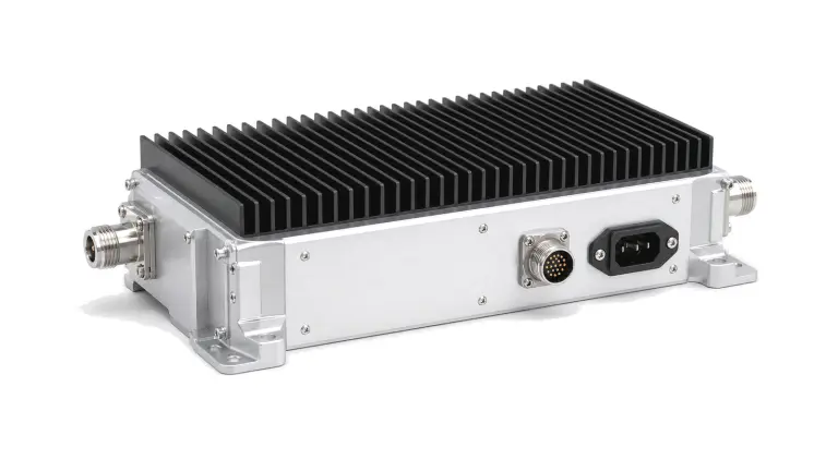
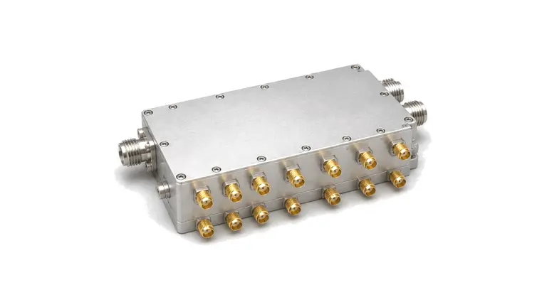
Tactical Communications RF Chain RF solution visual

RF path for mobile and field radios

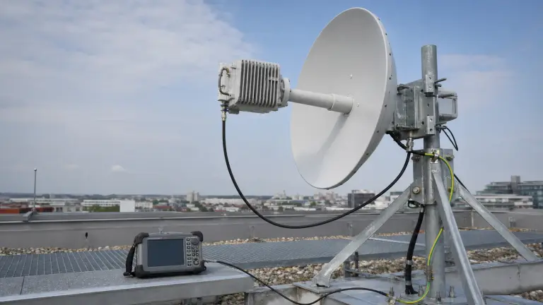
A tactical communications RF chain brings the receiver front end, transmitter drive path, power amplifier stage, RF switch, bandpass filtering, supply conversion and antenna interface into one compact communication path. It is used where radios, data links or telemetry equipment must keep stable RF behavior while the platform, supply and antenna environment change.

Chain boundary

The chain is shaped by operating band, channel spacing, transmit level, receive sensitivity, filter response, switch state, connector format, supply voltage, current demand, thermal path and enclosure size. These values define how the RF modules work together inside a portable, vehicle-mounted, airborne or field-deployed communication unit.

Integration inputs

Typical inputs include frequency coverage, output power, gain, noise figure, switching logic, antenna port requirement, supply range, control interface, environmental exposure and the test condition used to confirm link performance.
Articles

FAQ

How are environmental and EMC tests tailored for rail, maritime, road and airborne RF hardware?

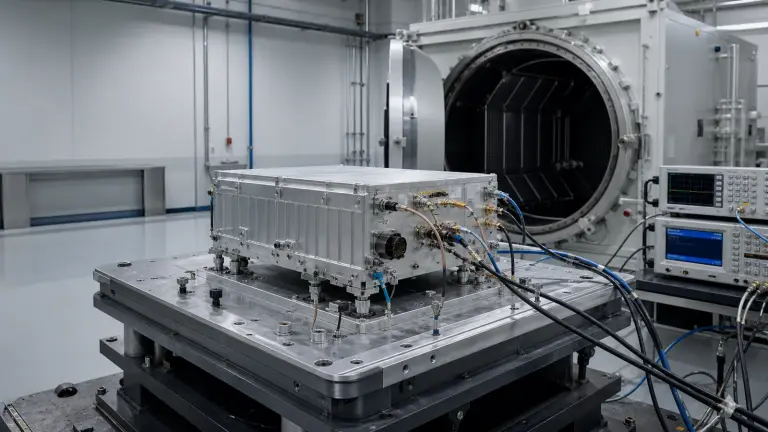
Derive test category, severity, axes, harness, operating modes and pass criteria from the exact installation rather than treating a platform standard as a universal certificate.

Why can an installed antenna pattern differ from the free-space data sheet?

Ground planes, structures, cables, radomes and mounting tolerances change current distribution and scattering, which can alter match, gain, pattern, polarization and phase center.

Engineering inquiry

Share your RF requirement

Share the product, operating requirements and project context. Our engineering team will route your request to the right specialist.

AttachmentsAttach drawings, BOMs, specifications or test files. Up to 5 files, 10 MB each and 25 MB total.
or drag and dropPDF, DOCX, XLSX, CSV, TXT, JPG, PNG, S1P and S2P
Typically reviewed within one business dayProject information is handled confidentially