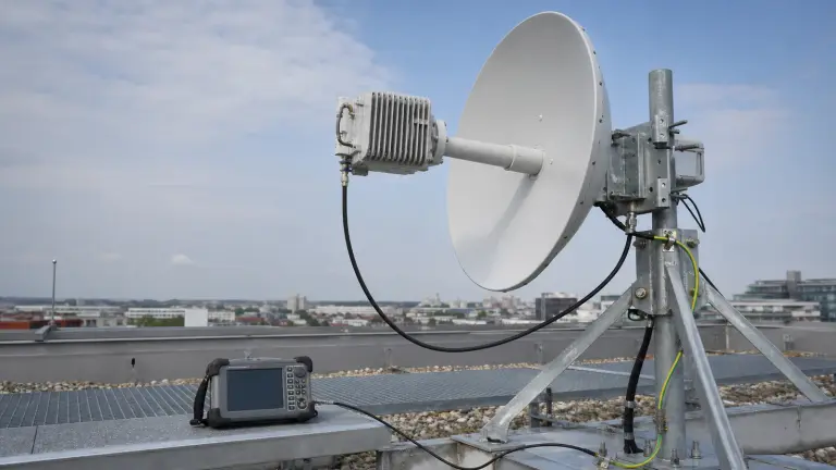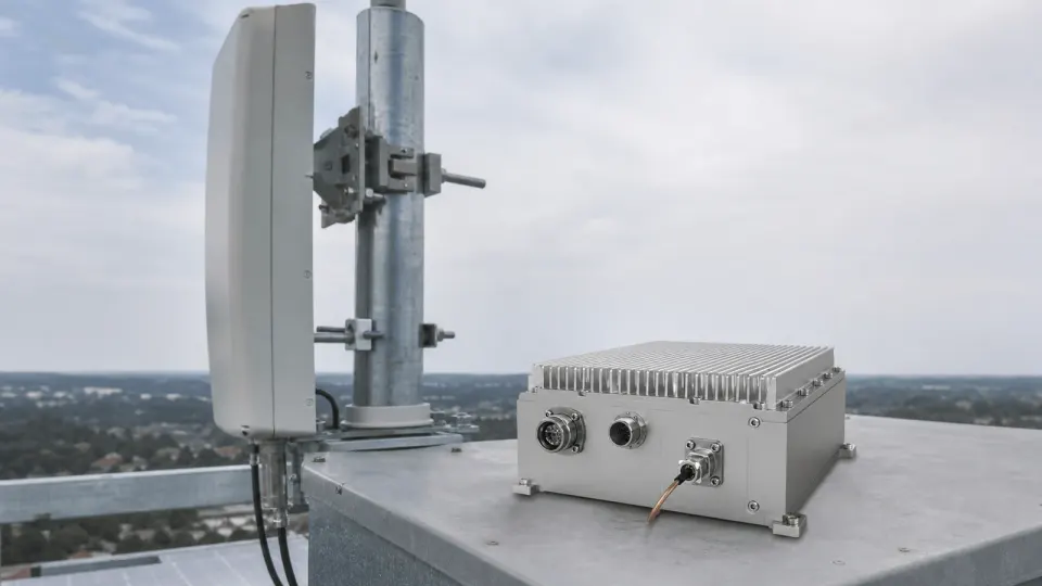
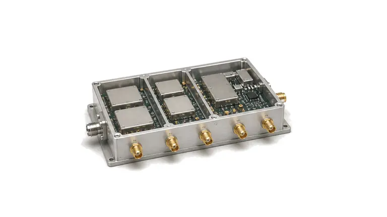
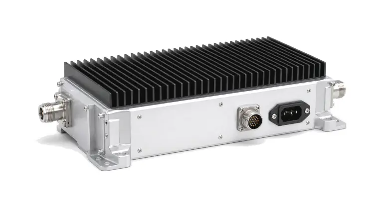
What does a base-station RF-chain architecture need to define?
It must allocate every transmit, receive, timing and control requirement from the radio interface to the antenna reference plane. The chain may include converters or RF transceivers, drivers, power amplifiers, feedback receivers, duplexers or TDD switches, limiters, LNAs, filters, distribution networks and an active or passive antenna system. A useful architecture is not a block diagram alone: each block owns part of the gain, noise, linearity, emission, phase, power, thermal and fault budget, with test points and calibration paths defined before hardware is frozen.
Freeze the standard profile and deployment boundary
Name the applicable 3GPP release, operating bands, regional requirements, channel bandwidths, subcarrier spacing, base-station class and conducted or radiated test configuration. Define TDD or FDD, sector count, antenna ports, transmit and receive paths, array size, polarization and whether the radio is a conventional remote unit or an active antenna system. If open fronthaul is required, state the O-RAN profile, functional split, synchronization and interoperability scope. For 6G work, cite the specific study or released normative profile; a future frequency range or spare processing margin is design intent, not evidence of 6G compliance.
Allocate transmit and receive budgets at the antenna plane
On transmit, work backward from per-port or per-beam EIRP through antenna gain, feeder and filter loss to required amplifier output. Include waveform crest factor, average power, back-off, digital predistortion headroom, gain variation, efficiency, EVM, ACLR, occupied bandwidth, unwanted emissions, harmonics and spurious response. On receive, allocate noise figure, gain, sensitivity, dynamic range, blocker tolerance, intermodulation, duplex isolation and limiter recovery from the antenna to the converter. TDD switching time and leakage can corrupt the first receive symbols. For arrays, set amplitude and phase matching, group-delay skew and calibration stability across channels and temperature.
Close timing, control, power and thermal interfaces
Define reference frequency accuracy, phase noise, time alignment and holdover together with the selected synchronization path, such as PTP, SyncE or an external frequency and pulse reference where required. Specify bias rails, sequencing, peak current, converter clocks, control latency, telemetry, fault thresholds and safe shutdown. The thermal model must cover simultaneous traffic, PA dissipation, filter and switch loss, converter load, enclosure resistance, airflow or conduction path and solar or ambient extremes. Map hot-spot temperature to gain, phase, EVM, output power and reliability; a room-temperature bench result is not a radio-unit thermal qualification.
Validate the chain with representative traffic and failure cases
Use the intended carrier aggregation, resource loading, modulation, power level and TDD pattern. Measure output power, EVM, ACLR, spectral emissions, spurious response, efficiency and predistortion convergence at the declared plane. Verify receiver sensitivity, dynamic range, blocking, intermodulation and recovery after transmit leakage. Conducted tests establish component budgets; over-the-air tests are required where the antenna and RF electronics form one system, including beam EIRP, pattern, polarization and calibration. Repeat across supply and temperature, exercise timing loss, fan or sensor faults and mismatch protection, and retain calibration files, software versions, uncertainty and pass/fail evidence by RF path.
- 3GPP release and profile, bands, regional rules, bandwidth, duplex mode, station class and test configuration
- Sector, port and MIMO path count, array and polarization, antenna reference plane and conducted or OTA boundary
- Transmit EIRP, average and peak power, back-off, EVM, ACLR, emissions, spurious and efficiency budgets
- Receive noise figure, gain, sensitivity, blocker, intermodulation, isolation, switching recovery and dynamic range
- Frequency and time reference, phase coherence, fronthaul profile, control, bias, telemetry, thermal and protection
- Waveforms, loading, temperature, supply, mismatch, fault cases, calibration, uncertainty and path-level acceptance records
Solution boundary
The engineering scope covers the integrated RF architecture of an infrastructure base station, radio unit or active antenna system from conversion and timing interfaces to the antenna plane. It does not define a handset RF front end, a generic network-deployment plan, a standalone antenna or amplifier category, or claim 6G compliance without a named normative profile and test basis.