Treat reception and timing as one evidence chain
A defensible requirement follows the signal from the antenna installation to the final clock consumer and assigns a measurable boundary to every conversion, steering and distribution step. A strong receiver cannot recover loss, overload or delay variation that was never controlled ahead of it, and a stable oscillator cannot prove timing continuity when outage state, temperature and path delay are undefined.
Define the service, operating environment and loss-of-signal behavior
List the constellations, civil signals, frequency bands and simultaneous combinations the equipment must use. State whether the system supports basic navigation, multi-frequency positioning, fixed timing, time transfer or a holdover-dependent network. These uses do not share one antenna bandwidth, phase-center requirement, interference case or timing acceptance limit. Tie signal definitions to the current interface specification instead of copying a legacy center frequency from an old design.
Describe sky view, mounting location, ground plane, radome, nearby transmitters, cable route, temperature, vibration, lightning or ESD boundary and available antenna power. Then define what the system must do during degraded reception: continue tracking, raise an alarm, enter holdover, reject time steps or declare the output invalid. Availability and recovery are engineering states, not adjectives.
Freeze the antenna-to-receiver reference plane
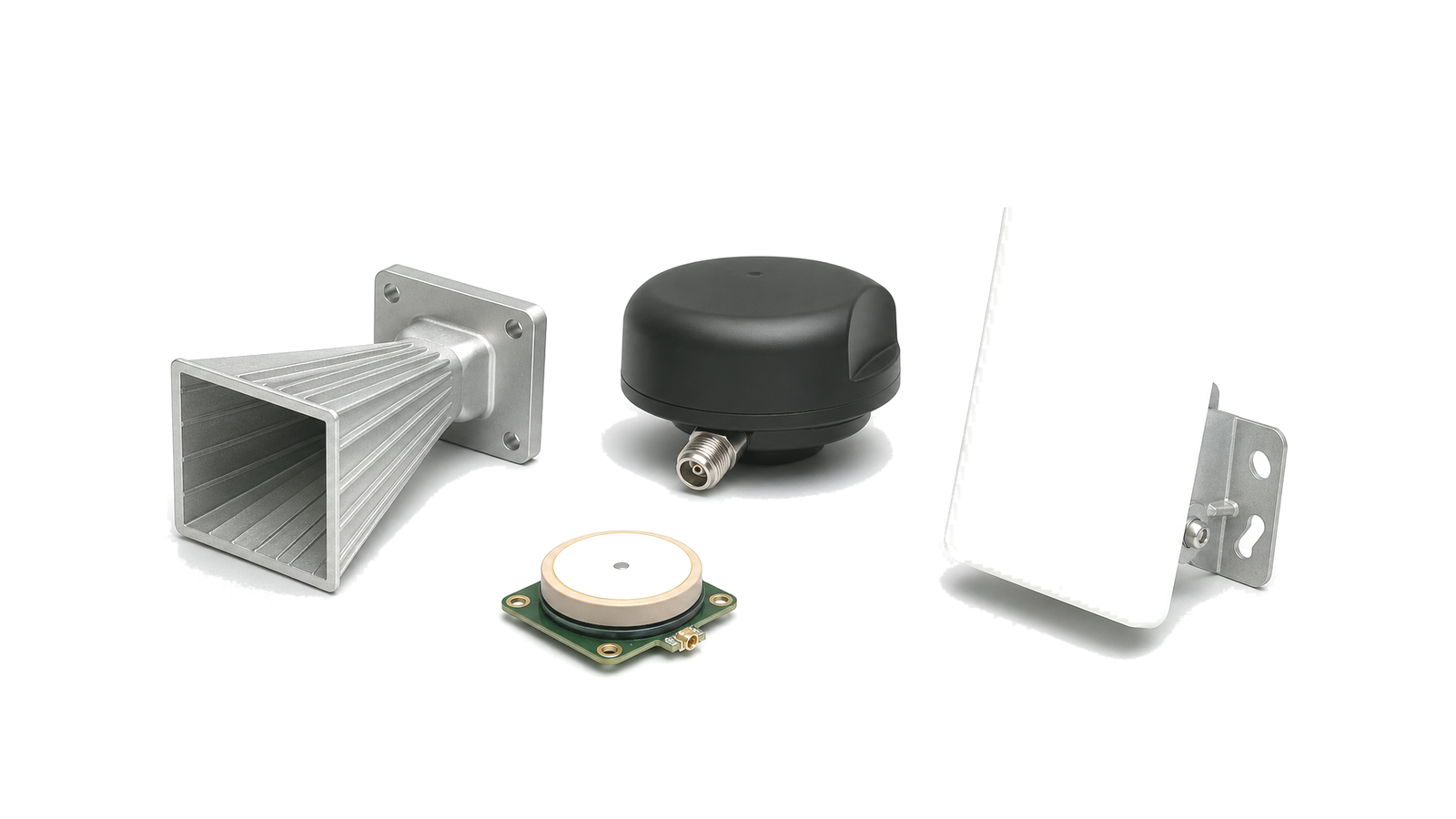
Name the antenna class, polarization, supported bands, gain pattern, axial ratio where relevant, phase-center behavior, multipath controls and installation datum. For an active antenna, include LNA gain and noise figure, supply voltage and current, bias injection, current monitoring, open- or short-circuit response, ESD protection and maximum safe input. The radome and ground plane are part of the delivered antenna behavior when they alter pattern or phase center.
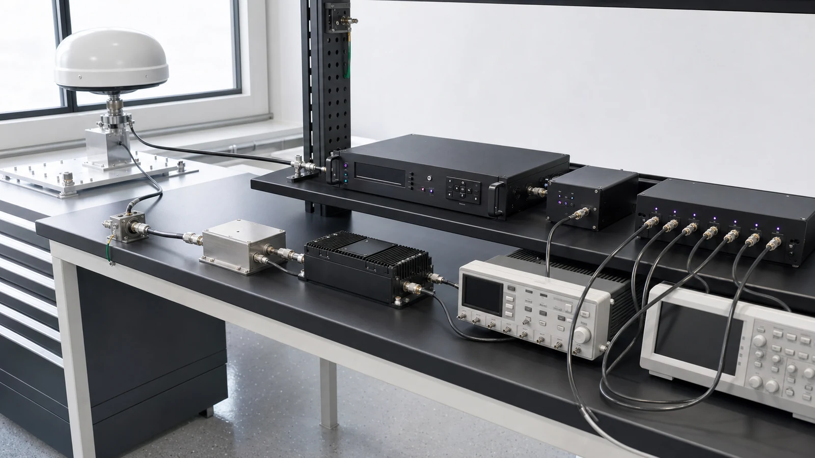
Draw every element between the antenna connector and receiver input: cable, surge protector, bias tee, splitter, coupler, filter, LNA, limiter and adapter. Record connector types, cable construction, length, insertion loss, return loss and delay at the relevant temperature. State whether the receiver specification begins at its own RF connector or at the installed antenna; otherwise link margin and absolute timing delay will be counted twice or not at all.
Allocate weak-signal margin and blocker tolerance together
Build the RF budget in physical order. Passive loss before the first effective LNA directly raises the cascaded noise figure, while too much front-end gain can reduce headroom under a nearby transmitter. Include antenna gain over elevation, cable and filter loss, LNA gain and noise, component compression or overload, receiver input range and ADC or AGC behavior. Evaluate the minimum and maximum gain states, not only a nominal room-temperature path.
Blocker tolerance needs a waveform and reference plane. Define interferer frequency or sweep, modulation, continuous or pulsed behavior, bandwidth, duty cycle, polarization or coupling path, input power, simultaneous wanted-signal condition and exposure time. Choose a result that can be measured, such as acquisition time, tracking continuity, C/N0 degradation, timing error, AGC state, data validity or recovery time. A label such as anti-jam or high rejection is not an acceptance test.
Separate acquisition, discipline, holdover and recovery
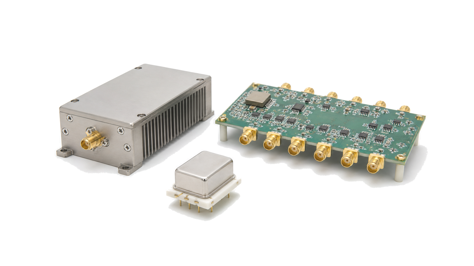
A GNSS-disciplined timing unit combines receiver-derived time with a local oscillator and steering loop. Specify initial lock conditions, warm-up, survey or fixed-position behavior, allowed phase correction, loop response, output validity and alarm timing. The local oscillator normally carries short intervals while the satellite reference supplies long-term alignment; temperature transients, aging and steering parameters affect how those roles meet.
Define holdover with a starting state, outage duration, temperature profile, supply condition, oscillator history and maximum accumulated time or phase error. Include the required frequency stability statistic and averaging interval when frequency output matters. State how the system detects reference loss, freezes or adapts steering, qualifies the output, reacquires the signal and prevents an uncontrolled phase step on recovery.
Specify PPS, frequency and time-code distribution at the load
For each output, define signal type, nominal frequency, logic or sine level, impedance, edge rate, duty cycle, connector, load, fan-out and isolation. A one-pulse-per-second output, a 10 MHz reference and a digital time code carry different information and fail differently. Identify whether outputs must be phase aligned, independently adjustable, monitored or hot-swappable, and whether unused outputs are terminated.
Create a delay budget from antenna phase center through receiver processing and every distribution path to the consumer connector. Separate fixed calibrated delay from temperature drift, channel skew, cable replacement and load-dependent change. Absolute timing needs traceable delay calibration; relative synchronization still needs repeatable skew and phase-noise evidence. Store per-channel compensation and hardware revision with the acceptance data.
Verify normal operation, impairment, holdover and return to service
Use four linked tests: a conducted RF path test at a declared receiver plane, an installed antenna and coexistence check, a controlled reference-loss and holdover test, and an end-to-end timing-output measurement at the real load. Exercise minimum signal, representative blockers, antenna power faults, cable or splitter states, temperature transitions, reference loss, restart and reacquisition. Preserve the conditions that make each result comparable.
Retain signal configuration, interferer state, RF level uncertainty, antenna and cable identity, firmware, oscillator state, temperature, raw timing or phase data, stability statistic, alarm logs, compensation values and pass/fail limits. Reverify after antenna relocation, cable replacement, filter or LNA change, firmware or steering update, oscillator service or any event that changes the reference plane or delay model.
| Decision boundary | Requirement to freeze | Reject the proposal when |
|---|---|---|
| Signals and service | Constellations, bands, simultaneous signals, use mode and loss-of-signal state | Only GNSS compatible is stated |
| Antenna installation | Pattern, polarization, phase center, ground plane, radome, location and nearby transmitters | A catalog antenna is assumed to behave the same in every installation |
| RF path | Every cable, bias, protection, filter, gain and reference-plane transition | Sensitivity is quoted without the installed path |
| Interference | Waveform, frequency, level, duty cycle, coupling plane, wanted signal and degradation metric | Anti-jam or blocker tolerant has no reproducible test |
| Local reference | Oscillator, warm-up, steering, stability statistic, observation interval and alarms | One accuracy number mixes short- and long-term behavior |
| Holdover | Starting state, outage, environment, maximum time error and recovery rule | Holdover is quoted without duration or temperature |
| Distribution | PPS or frequency interface, load, fan-out, delay, skew, phase noise and compensation | Timing accuracy stops at the receiver output |
| Evidence | Raw data, configuration, uncertainty, serials, revisions and re-verification triggers | Only a screenshot or pass label is delivered |
Worked decision: an active antenna can improve sensitivity and still worsen coexistence
Consider a roof antenna feeding a long coax cable into a timing receiver installed beside a cellular transmitter. Placing low-noise gain at the antenna can overcome cable loss, but the same gain may drive the LNA, filter or receiver toward compression when the nearby transmitter is active. The correct requirement therefore defines antenna gain and noise, cable loss, preselector location, out-of-band input, LNA linearity, receiver AGC or overload indication, wanted-signal state and recovery metric at named planes. The timing test then repeats the coexistence state while measuring output validity and time error; a clear-sky sensitivity number alone does not close the design.

Verify the chain from antenna interface to the timing consumer
- Approve constellation, signal, band, simultaneous-operation, use-mode and degraded-service requirements.
- Freeze antenna type, installation datum, ground plane, radome, nearby emitters and environmental boundary.
- Draw the complete RF path and record cable, protection, bias, filter, LNA, splitter and receiver reference planes.
- Calculate minimum and maximum gain, cascaded noise, loss, linearity and active-antenna power conditions.
- Define conducted and coupled blocker cases with wanted-signal state, metric, exposure and recovery limits.
- Measure acquisition, tracking, timing validity and recovery at the declared RF input condition.
- Characterize oscillator warm-up, steering, stability and alarm behavior over named observation intervals.
- Run holdover from a controlled starting state through the required outage and temperature profile.
- Measure PPS or frequency-output delay, skew, phase noise and load behavior at every delivered channel.
- Archive raw RF and timing data, configuration, uncertainty, serial identity, compensation and last valid verification.
Failures hidden by a generic GNSS receiver requirement
- Selecting bands without the current signal interface and simultaneous-use requirement
- Ignoring ground plane, radome, cable route or nearby transmitters in the antenna decision
- Quoting receiver sensitivity at its connector as installed-system sensitivity
- Adding LNA gain without checking blockers, compression and recovery
- Using one unspecified interference level as proof of receiver immunity
- Treating AGC or lock indication as proof that timing data remain valid
- Quoting oscillator accuracy without observation interval, environment or steering state
- Publishing holdover without outage duration, starting condition and maximum time error
- Ignoring receiver, cable and distribution delay when claiming absolute timing
- Changing antenna, cable, firmware or compensation without end-to-end re-verification
Information required for a GNSS receiver and timing-chain RFQ
- Target constellations, civil signals, bands and simultaneous combinations
- Navigation, fixed-timing, time-transfer or synchronization use mode
- Antenna form, polarization, pattern, phase-center and installation constraints
- Radome, ground plane, cable route, length, connector and environmental limits
- Active-antenna voltage, current, bias, fault monitoring, ESD and protection requirements
- Filters, LNAs, limiters, splitters and the declared receiver input reference plane
- Minimum signal, acquisition, tracking, C/N0, data-validity and recovery criteria
- Nearby transmitter inventory and conducted or coupled blocker waveforms
- Minimum and maximum gain, loss, noise figure, linearity and overload boundaries
- Local oscillator, warm-up, discipline loop, phase correction and alarm behavior
- Holdover starting state, outage duration, temperature profile and maximum time error
- PPS, 5 or 10 MHz, clock and time-code interfaces, levels, loads and fan-out
- Fixed delay, delay drift, channel skew, phase noise and compensation method
- Required raw data, uncertainty, calibration, configuration, traceability and change-control records
Continue the navigation and timing engineering decision
- Review navigation, timing and positioning RF applications
- Review GNSS and BeiDou receiver paths
- Review precision timing distribution applications
- Review navigation RF front-end applications
- Review receiver front-end signal-chain solutions
- Review phase-coherent timing-chain solutions
- Read the RF signal-source requirement guide
- Send the antenna, interference, holdover and timing-distribution requirements