
LCRF

Privacy preferences

Choose optional purposes independently. You can change or withdraw your choice at any time from the footer.

Strictly necessary

Required for security, session functions and storing your privacy choice.

Always active
Preferences

Remembers optional display or language settings when these features are enabled.

Analytics

Uses first-party visitor and session identifiers to measure pages, referrals and inquiry interactions.

Marketing

Allows marketing measurement or third-party advertising technologies if they are introduced in the future.

Counter-UAS RF Subsystem

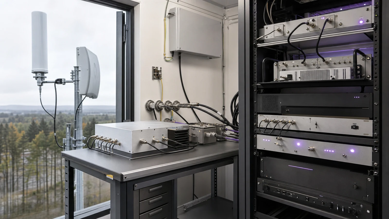
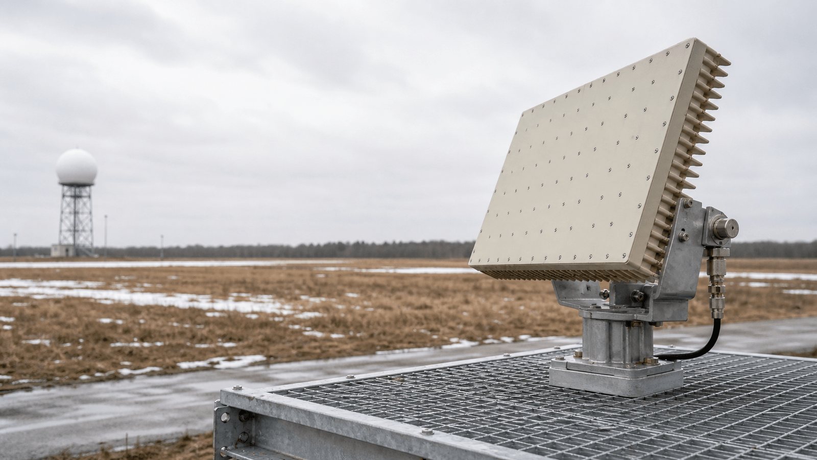
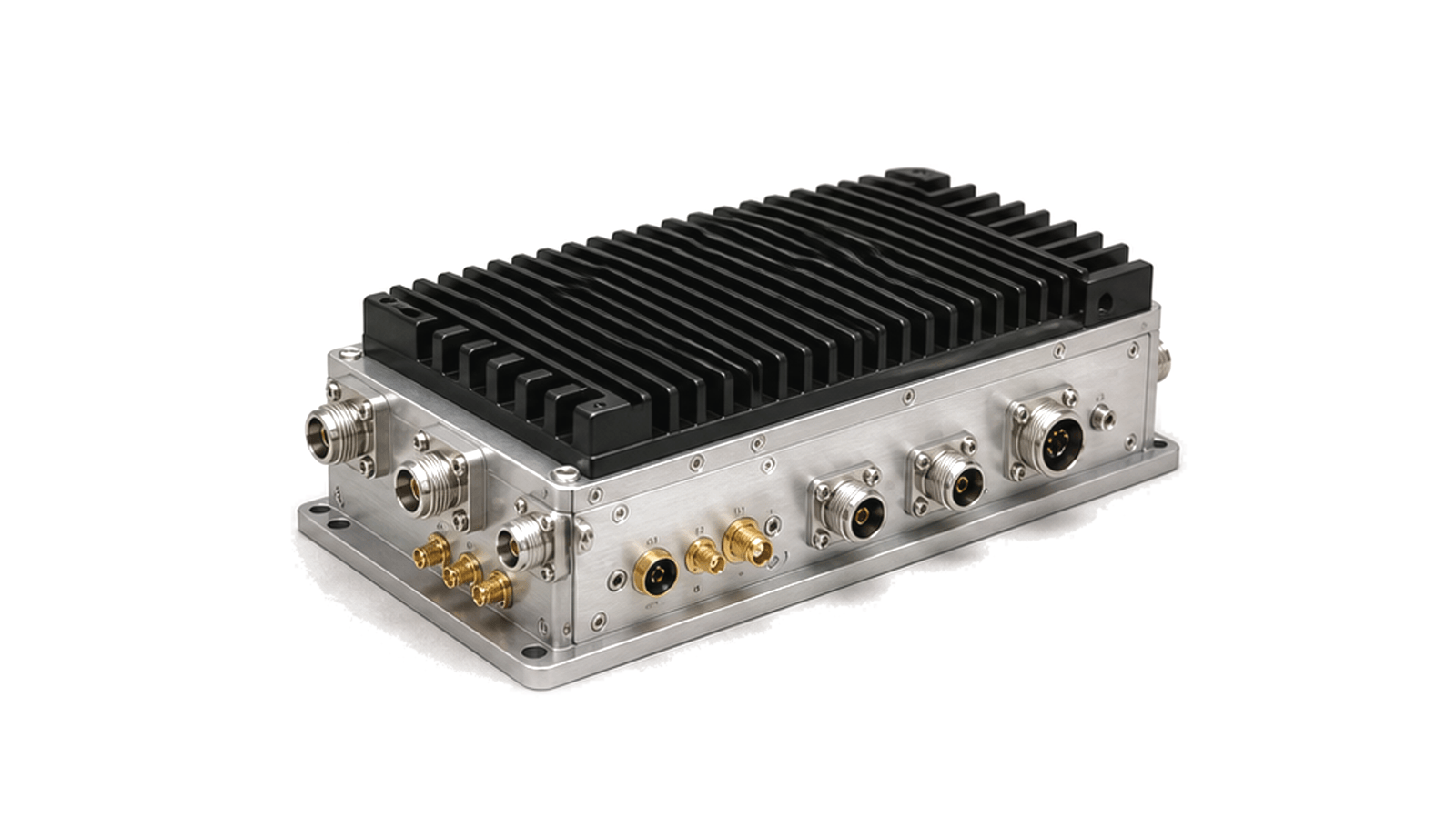
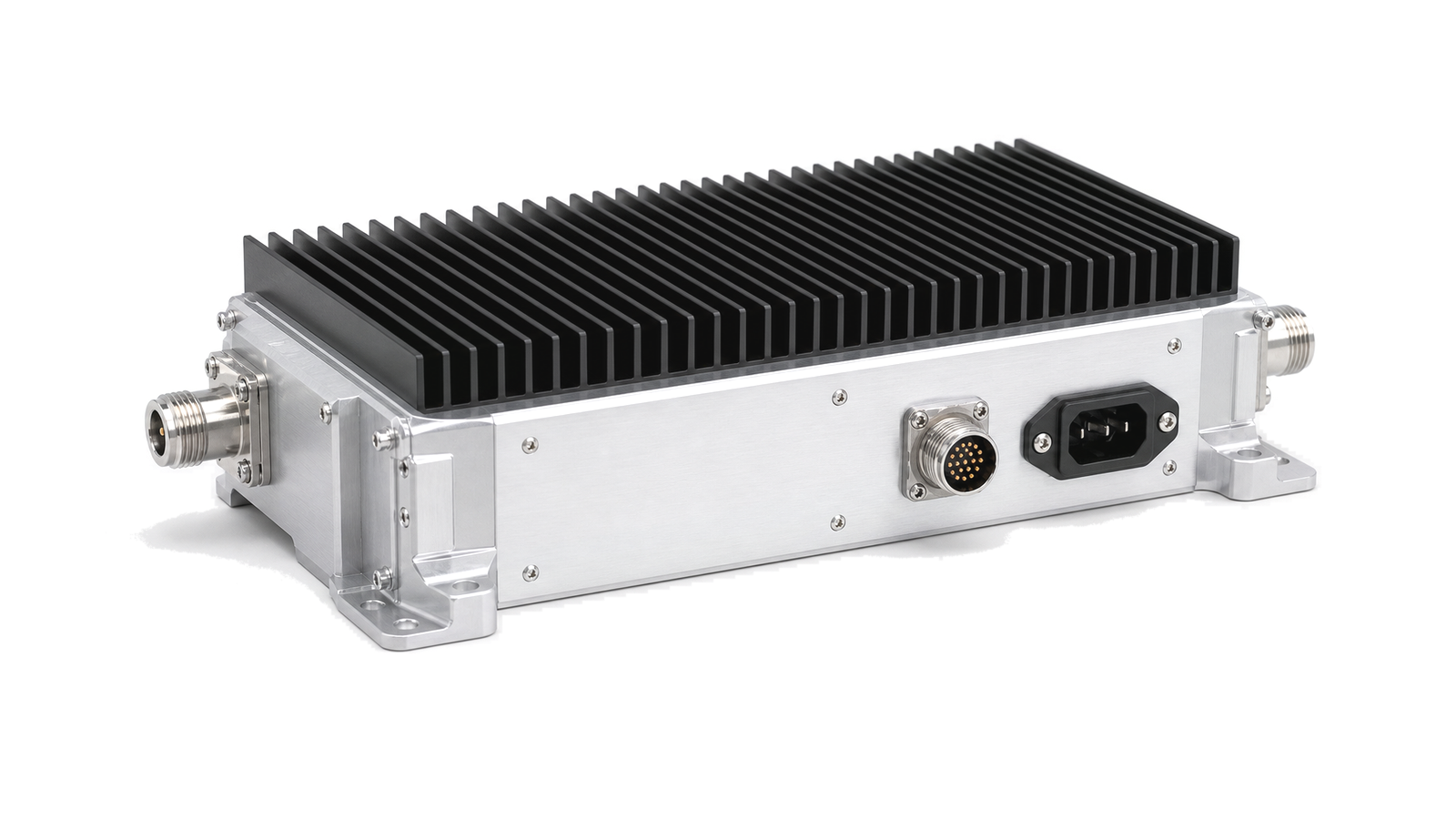
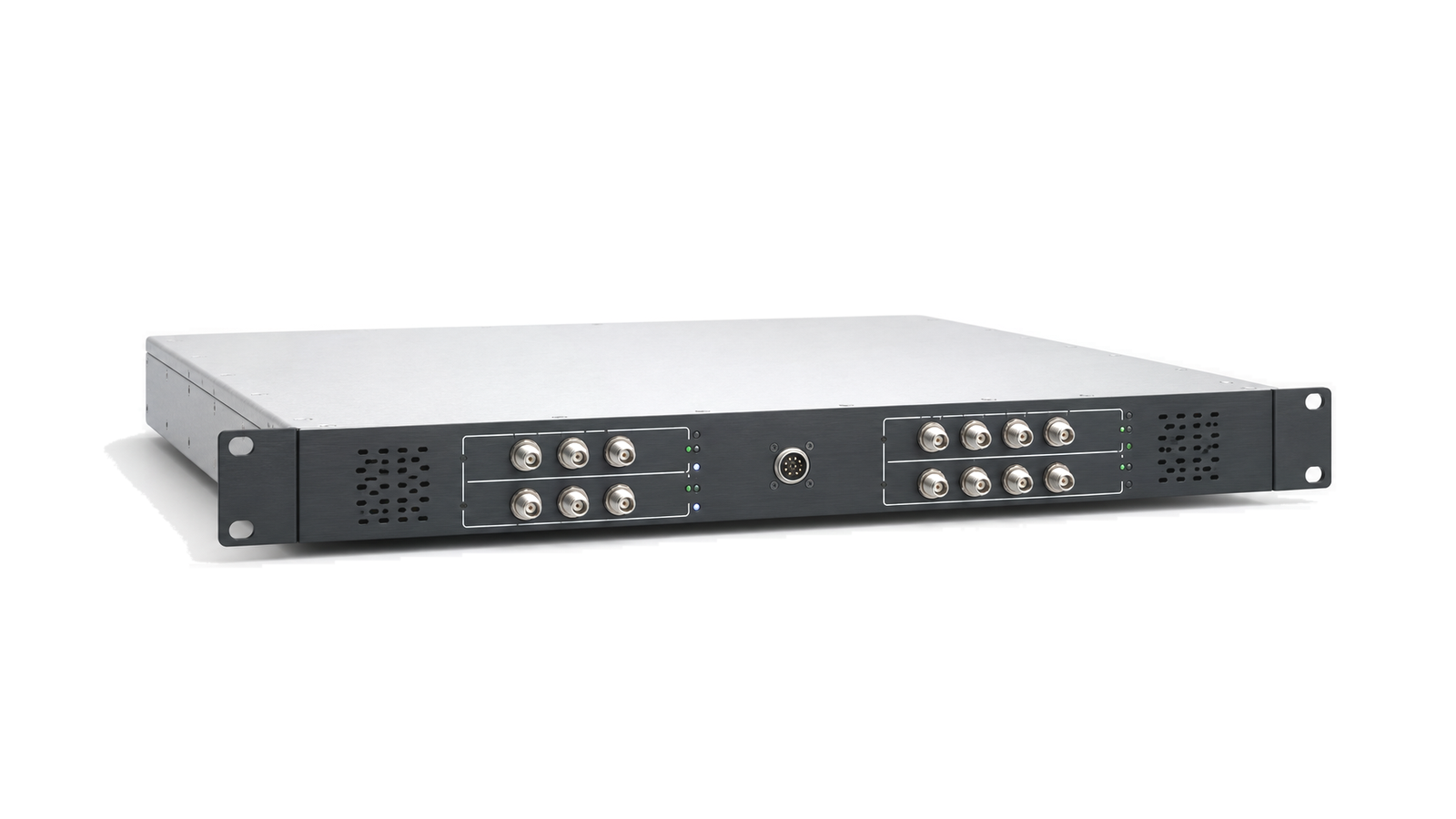
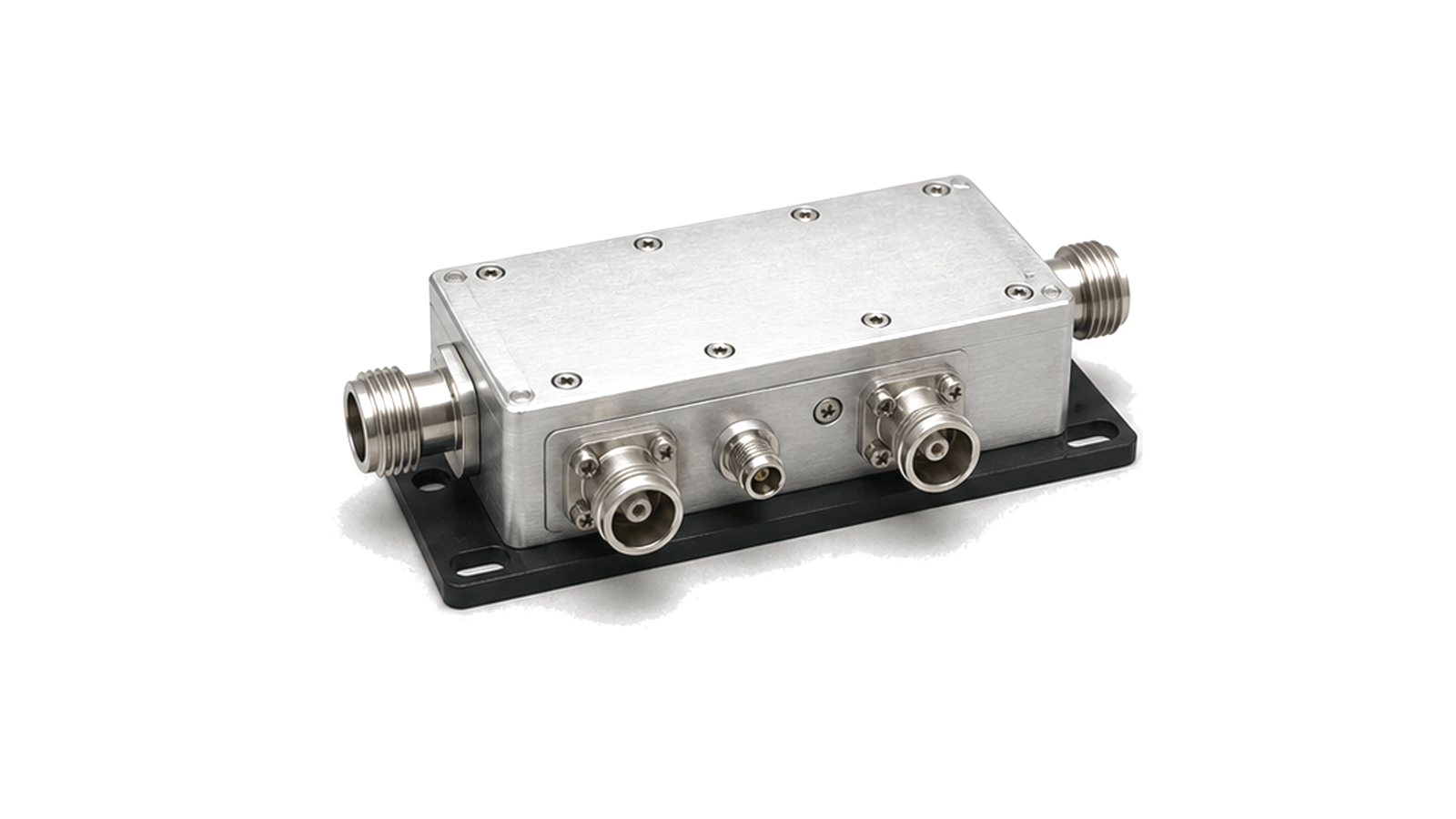
RF subsystem paths for authorized counter-UAS and drone-detection environments, covering antenna front ends, conversion, power stages and reflected-power monitoring.

Counter-UAS RF Subsystem RF solution visual

Counter-UAS RF Subsystem

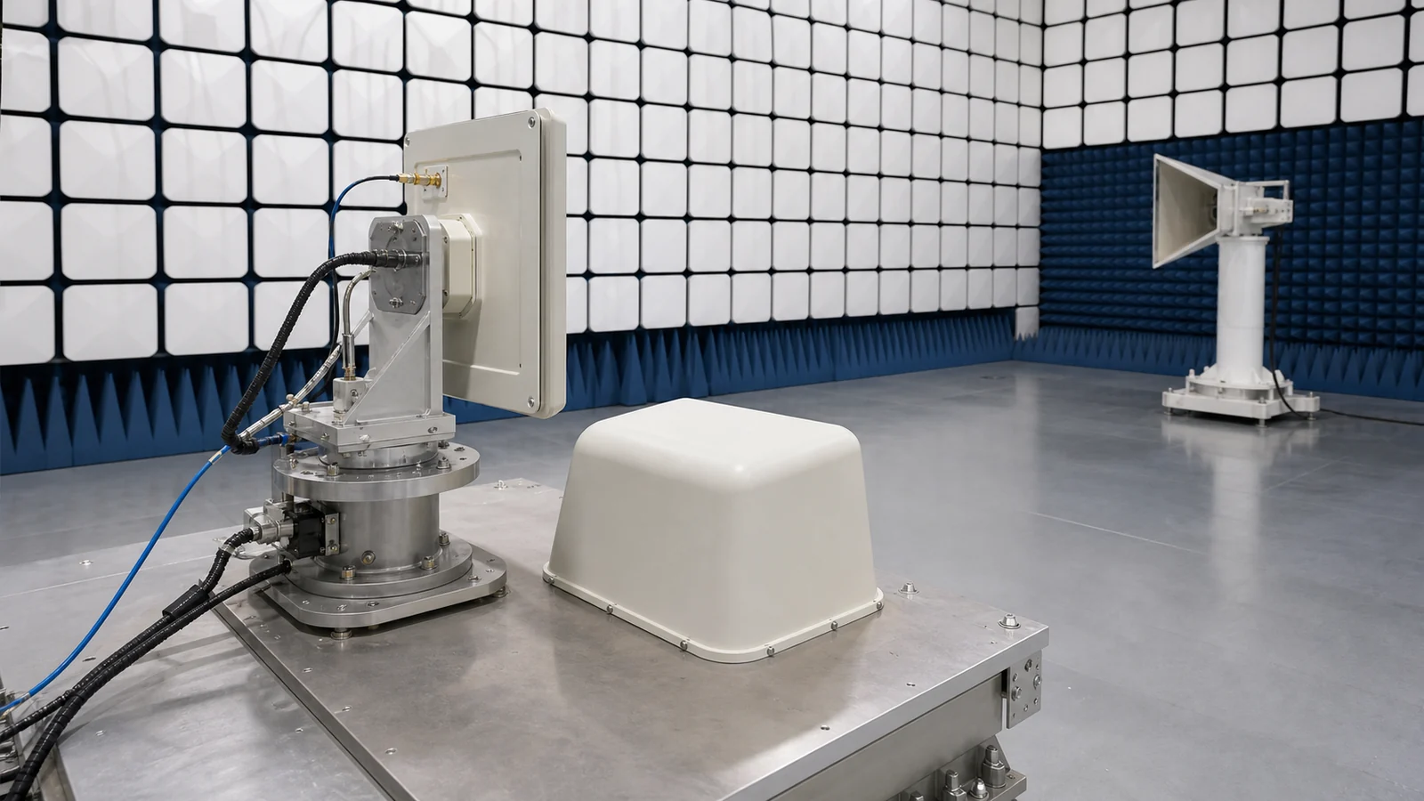
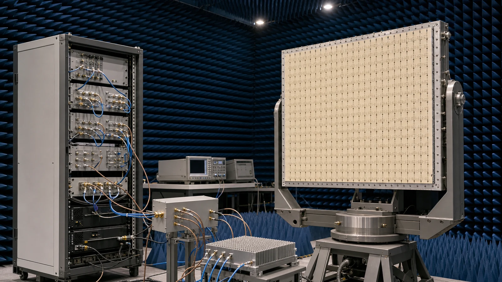
A counter-UAS RF subsystem brings antenna front ends, frequency conversion, power amplification and monitoring hardware into controlled receive or transmit paths for authorized drone-detection and mitigation environments. The same system boundary may include sensing channels, directional antennas, converter modules, RF power stages and reflected-power protection.

Signal-chain boundary

The chain is shaped by operating band, antenna coverage, conversion plan, output power, duty cycle, isolation, thermal path, VSWR response and control interface. These conditions determine how the RF hardware connects to detection equipment, command logic, antenna arrays or test fixtures.

Engineering data

Useful records include frequency coverage, channel plan, gain distribution, output level, antenna interface, switching state, protection threshold, monitor point, cooling method, enclosure requirement and compliance note for the final deployment environment.
Articles

FAQ

What must a radar Tx/Rx protection requirement include beyond receiver survival?

A complete Tx/Rx protection requirement includes survivable peak and average leakage, limiter and switch behavior, residual level, overload recovery, post-pulse gain/noise/phase and the nearest usable range gate.

How should the simultaneous signal environment be specified for a spectrum-monitoring receiver?

Define weak signals and every simultaneous strong emitter by frequency, waveform, bandwidth, level, duty cycle, timing, antenna or conducted coupling plane and required observation outcome.

How should preselection, blocker tolerance and overload limits be specified for a monitoring receiver?

Specify each band state by preselector rejection, insertion loss, gain or attenuation, noise figure, IP3 or compression, full-scale margin, overload indication and recovery under a simultaneous weak signal.

Engineering inquiry

Share your RF requirement

Share the product, operating requirements and project context. Our engineering team will route your request to the right specialist.

AttachmentsAttach drawings, BOMs, specifications or test files. Up to 5 files, 10 MB each and 25 MB total.
or drag and dropPDF, DOCX, XLSX, CSV, TXT, JPG, PNG, S1P and S2P
Typically reviewed within one business dayProject information is handled confidentially