
LCRF

Privacy preferences

Choose optional purposes independently. You can change or withdraw your choice at any time from the footer.

Strictly necessary

Required for security, session functions and storing your privacy choice.

Always active
Preferences

Remembers optional display or language settings when these features are enabled.

Analytics

Uses first-party visitor and session identifiers to measure pages, referrals and inquiry interactions.

Marketing

Allows marketing measurement or third-party advertising technologies if they are introduced in the future.

Navigation RF Front Ends

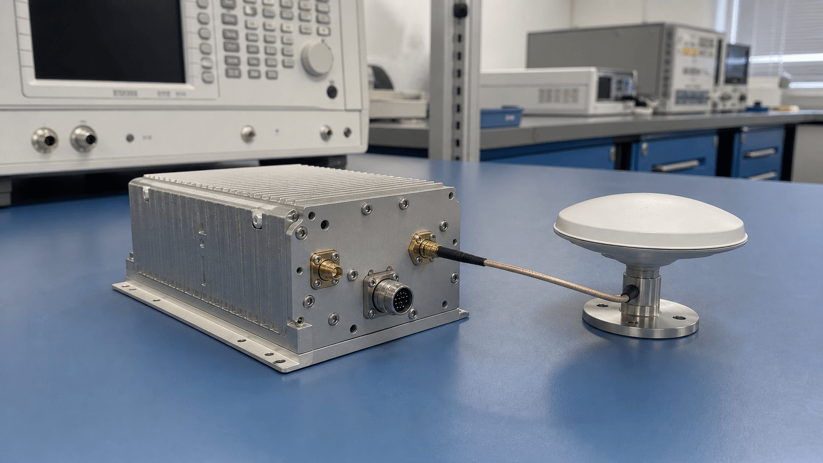
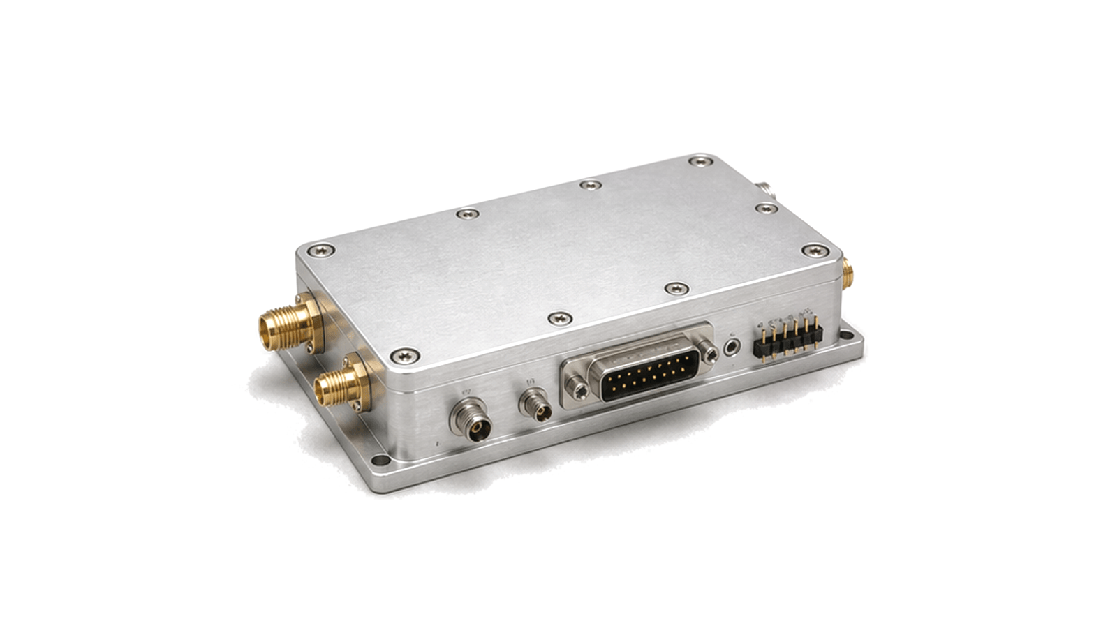
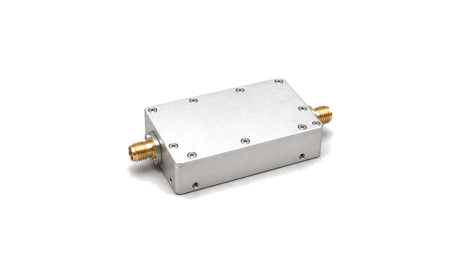
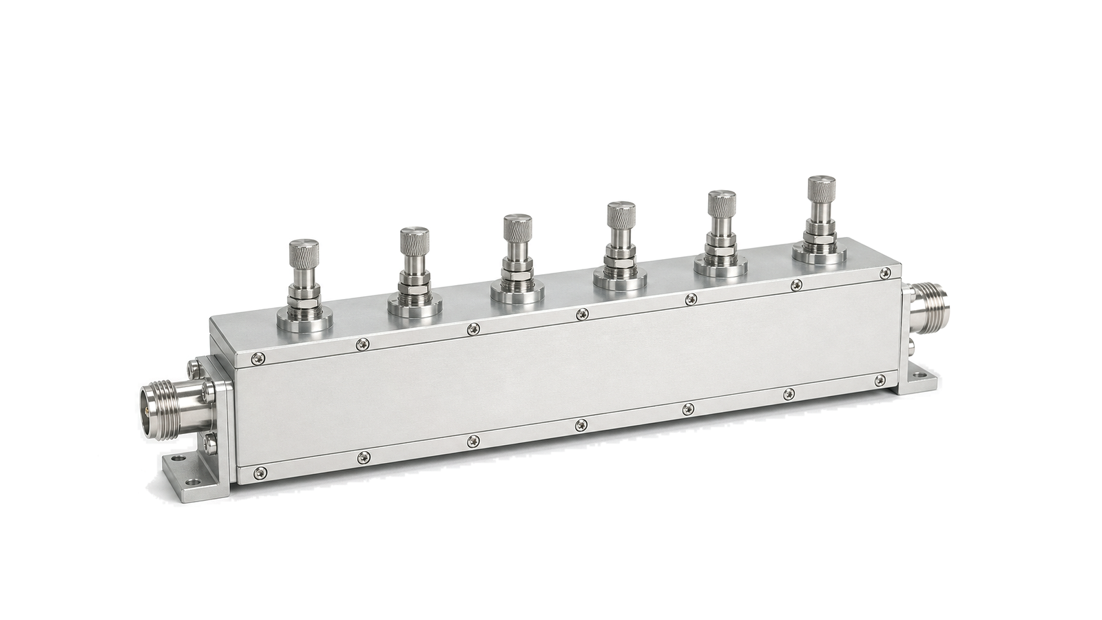
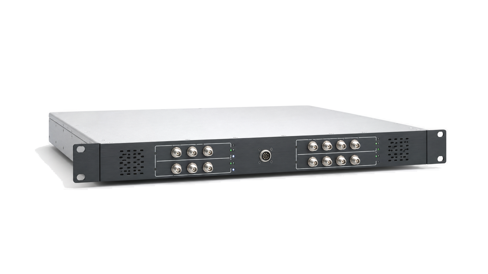
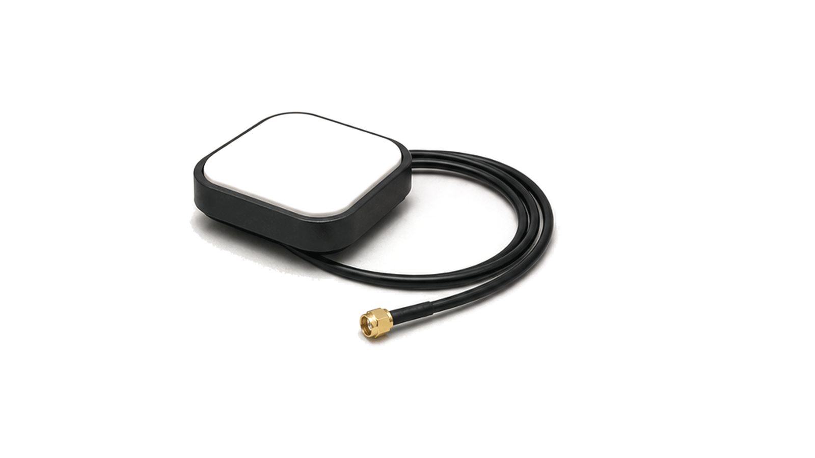
Navigation RF front ends capture weak GNSS, BeiDou and timing signals before receiver processing, combining antenna paths, low-noise gain and filtering.

Navigation RF Front Ends RF application visual

Receive paths for navigation and timing signals

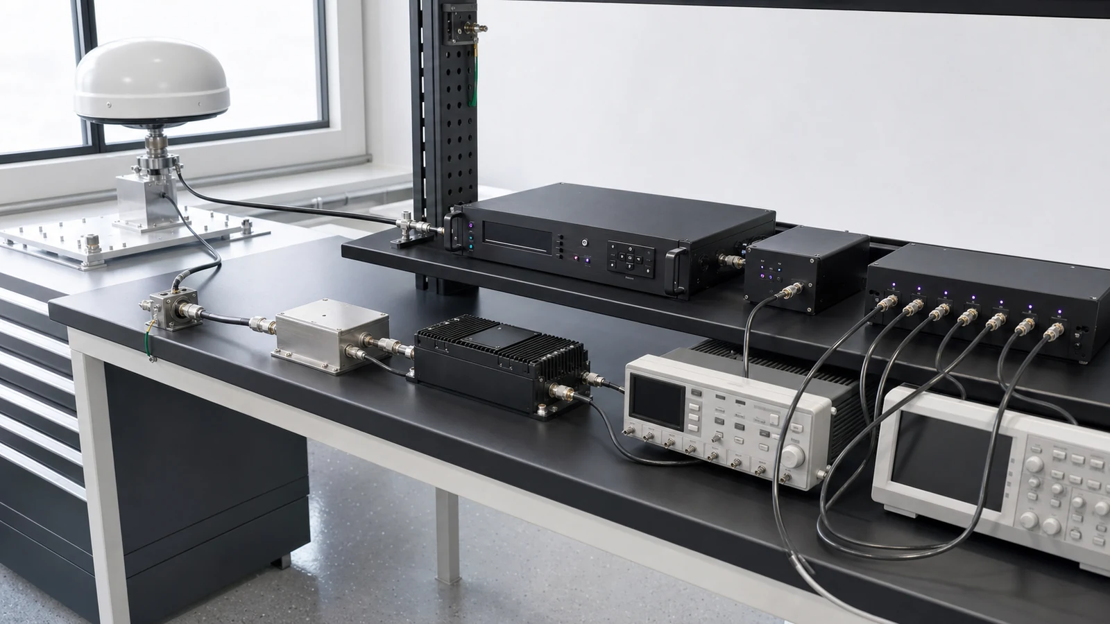
Navigation RF front ends sit between the antenna environment and the receiver or timing equipment. They handle weak GNSS, BeiDou and timing signals where cable loss, noise figure, filtering, interference exposure and reference stability directly affect usable data.

Engineering boundary

The application includes antenna placement, low-noise amplification, bandpass filtering, receiver modules and distribution paths used by fixed stations, mobile platforms, synchronized test systems and multi-channel RF equipment. The practical design boundary is shaped by signal level, out-of-band rejection, connector interface, environmental drift, distribution delay and the stability required by the downstream receiver.

Treat reception and timing as one evidence chain

RF hardware for Navigation RF Front Ends
Define the service, operating environment and loss-of-signal behavior List the constellations, civil signals, frequency bands and simultaneous combinations the equipment must use. State whether the system supports basic navigation, multi-frequency positioning, fixed timing, time transfer or a holdover-dependent network....
Navigation RF Front Ends RF requirements
Define the service, operating environment and loss-of-signal behavior List the constellations, civil signals, frequency bands and simultaneous combinations the equipment must use. State whether the system supports basic navigation, multi-frequency positioning, fixed timing, time transfer or a holdover-dependent network....
Navigation RF Front Ends RF architecture
Define the service, operating environment and loss-of-signal behavior List the constellations, civil signals, frequency bands and simultaneous combinations the equipment must use. State whether the system supports basic navigation, multi-frequency positioning, fixed timing, time transfer or a holdover-dependent network....
Navigation RF Front Ends RF hardware selection
Define the service, operating environment and loss-of-signal behavior List the constellations, civil signals, frequency bands and simultaneous combinations the equipment must use. State whether the system supports basic navigation, multi-frequency positioning, fixed timing, time transfer or a holdover-dependent network....
Navigation RF Front Ends RF testing and verification
Verify the chain from antenna interface to the timing consumer

How to Specify a GNSS Receiver Front End and Precision Timing Chain

A practical method for defining GNSS and BeiDou antenna paths, filtering, low-noise gain, receiver interference tolerance, disciplined references, holdover and PPS or 10 MHz distribution with measurable acceptance evidence.
GNSS RF Front-End & Precision Timing Specification

Articles

FAQ

What belongs in a GNSS antenna, LNA, filter and cable RF budget?

Budget antenna gain, pre-LNA loss, LNA noise and gain, filtering, cable loss, active-antenna power, return loss, linearity, receiver range and blocker headroom in physical path order.

How should PPS and 10 MHz timing-distribution delay and skew be verified?

Verify every delivered timing channel at its real load by separating fixed calibrated delay, channel skew, environmental drift, output level, edge or phase behavior and path-dependent uncertainty.

How should GNSS receiver blocker and interference tolerance be specified?

Define the interferer waveform, frequency, bandwidth, duty cycle, coupling plane, wanted-signal state, exposure and measurable degradation or recovery metric instead of relying on an anti-jam label.

What does holdover mean in a GNSS-disciplined timing system?

Holdover is the bounded time or frequency performance after GNSS reference loss, defined by the starting state, outage duration, environment, local oscillator, steering history, maximum time error and recovery rule.

Why can an installed antenna pattern differ from the free-space data sheet?

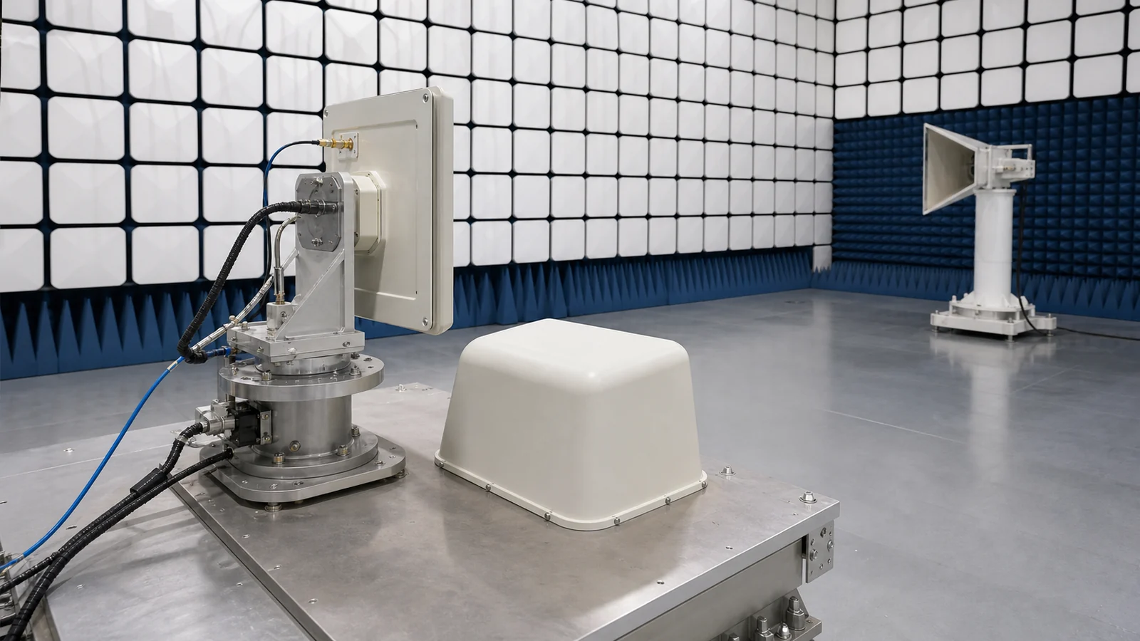
Ground planes, structures, cables, radomes and mounting tolerances change current distribution and scattering, which can alter match, gain, pattern, polarization and phase center.

How should linear, circular, axial-ratio and cross-polarization requirements be specified?

Define linear orientation or circular sense, the viewing and coordinate convention, axial ratio, cross-polar limits and the frequency and angular region where they apply.

What is the difference between antenna gain, directivity, beamwidth and sidelobes?

Directivity describes angular concentration, gain includes dissipative efficiency, beamwidth describes main-beam extent and sidelobes describe radiation outside that beam.

How are antenna VSWR, return loss, reflection coefficient and mismatch loss related?

VSWR, return loss and reflection coefficient express port mismatch; mismatch loss quantifies the accepted-power penalty, but none proves radiation efficiency or pattern.

Engineering inquiry

Share your RF requirement

Share the product, operating requirements and project context. Our engineering team will route your request to the right specialist.

AttachmentsAttach drawings, BOMs, specifications or test files. Up to 5 files, 10 MB each and 25 MB total.
or drag and dropPDF, DOCX, XLSX, CSV, TXT, JPG, PNG, S1P and S2P
Typically reviewed within one business dayProject information is handled confidentially