
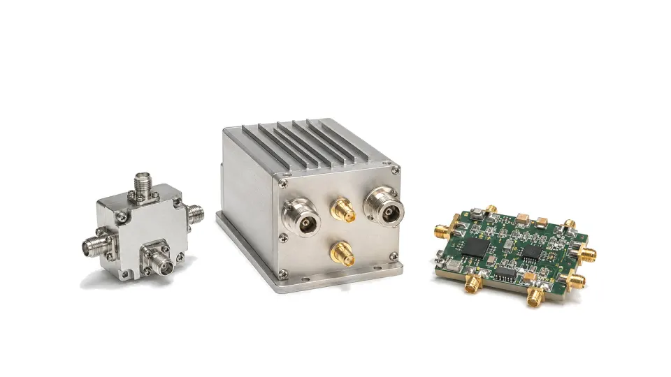
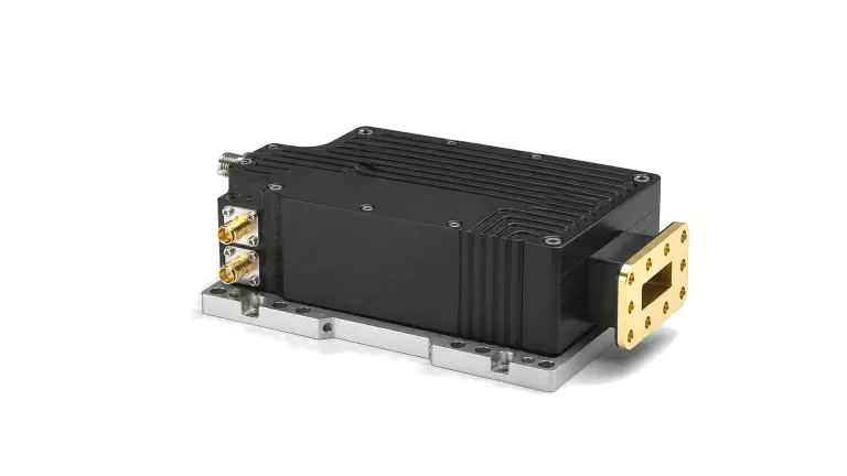
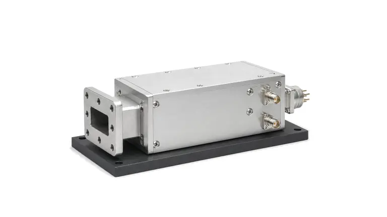
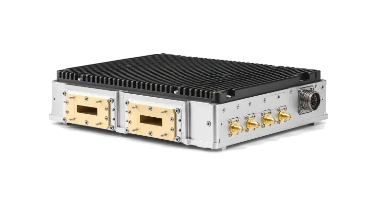
What is frequency conversion and IF processing?
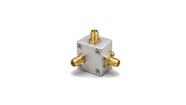
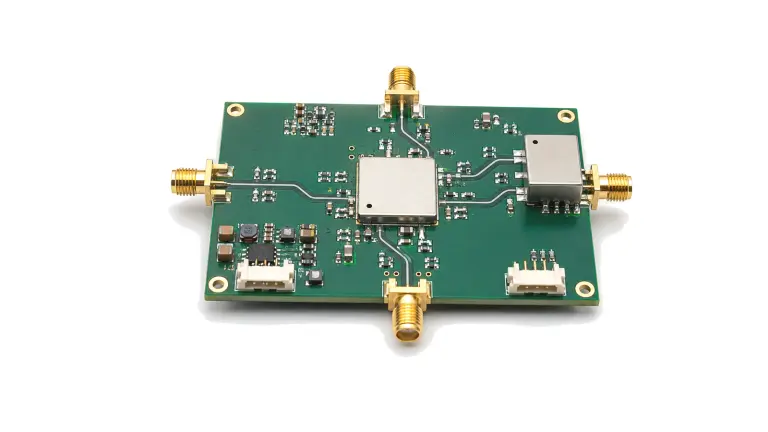
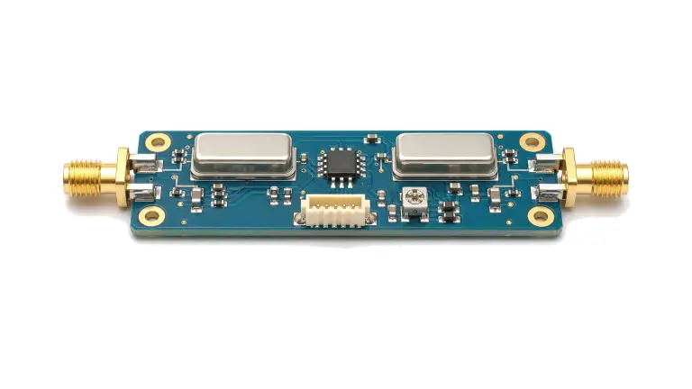
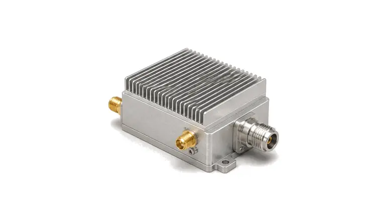
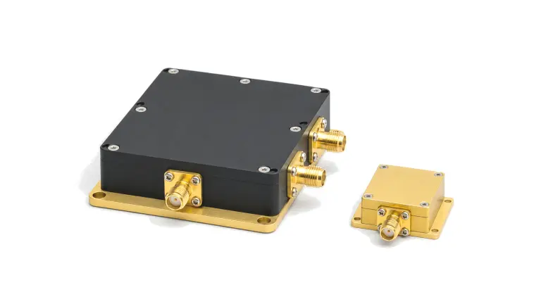
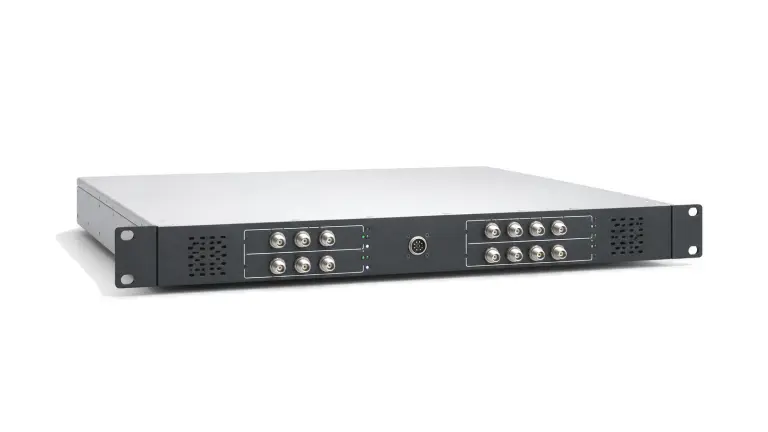
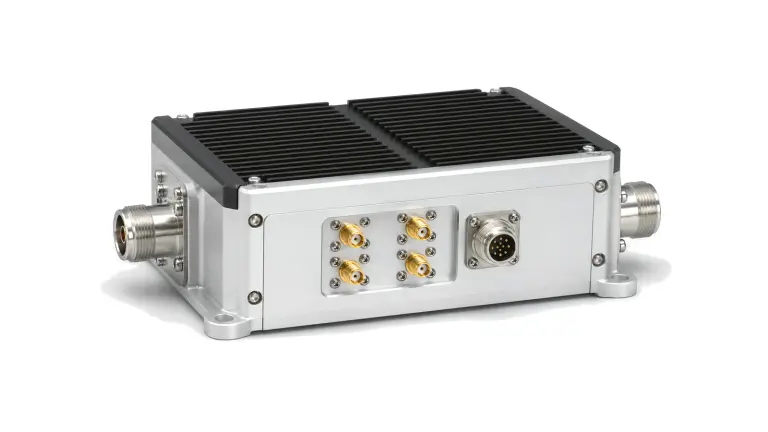
Frequency-conversion hardware translates a signal between RF, microwave, intermediate-frequency and baseband ranges while preserving the information needed by the receiver or transmitter. Mixers, upconverters, downconverters, transceiver converters, I/Q modules, multipliers, dividers and IF assemblies occupy different points in that path. Their performance is determined by the complete RF, LO and IF frequency plan, not by an input band alone.
How do you select frequency-conversion hardware?
Build a frequency plan before comparing modules. List wanted RF and IF bands, tuning steps, guard bands, image locations, LO range and drive level, then calculate the mixing products that can fall inside a protected band. Decide whether conversion gain or loss is acceptable and where filtering, amplification and switching sit relative to the converter. This exposes spurious and dynamic-range risks before hardware is selected.
| Decision area | Questions to resolve | Evidence to request |
|---|---|---|
| Frequency plan | Which RF, LO and IF combinations occur in every operating mode? | Band tables, tuning law, image map and blocked or reserved ranges |
| Signal level | Will wanted and unwanted signals remain inside the linear range? | Conversion gain or loss, P1dB, IP3, noise figure and maximum input |
| Spectral purity | Which harmonics, LO leakage and intermodulation products are permitted? | Spurious tables or plots under representative RF, LO and IF conditions |
| Interfaces | Are impedance, connectors, control, supply and timing compatible? | Port definitions, control protocol, phase-noise contribution and switching behavior |
Which technical specifications matter?
Input and output frequency ranges must be paired with the required LO range and power. Conversion gain or loss, gain flatness, noise figure, input and output match, compression and intermodulation define usable dynamic range. For I/Q paths, amplitude balance, phase balance, carrier leakage and sideband suppression become central. Wideband or agile systems also need switching time, phase continuity, settling behavior and mode-dependent spur data.
Spurious performance cannot be represented by one headline value. The result changes with RF input, LO frequency, IF selection, drive level and filtering. A useful specification therefore states the combinations tested, the measurement bandwidth and the reference planes. Where an untested tuning combination can create an in-band product, include it in qualification rather than assuming a nearby result applies.
Evaluating a frequency-conversion supplier or manufacturer
Request a frequency plan or spur table that matches the intended operating modes. Confirm whether quoted gain, noise and linearity limits are guaranteed across the complete band and temperature range or shown only as typical curves. Review LO generation, external filtering, calibration and control dependencies so that omitted functions are not discovered during integration. Mechanical, supply and thermal interfaces should be reviewed with the RF ports because they can change phase, settling and repeatability.
How is frequency-conversion hardware tested and verified?
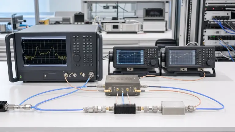
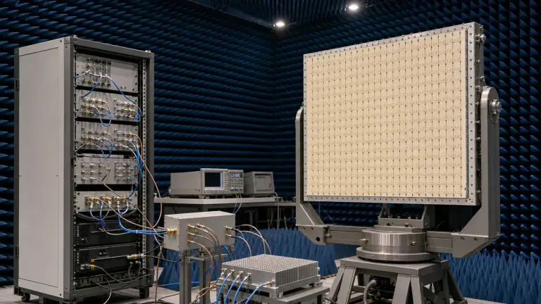
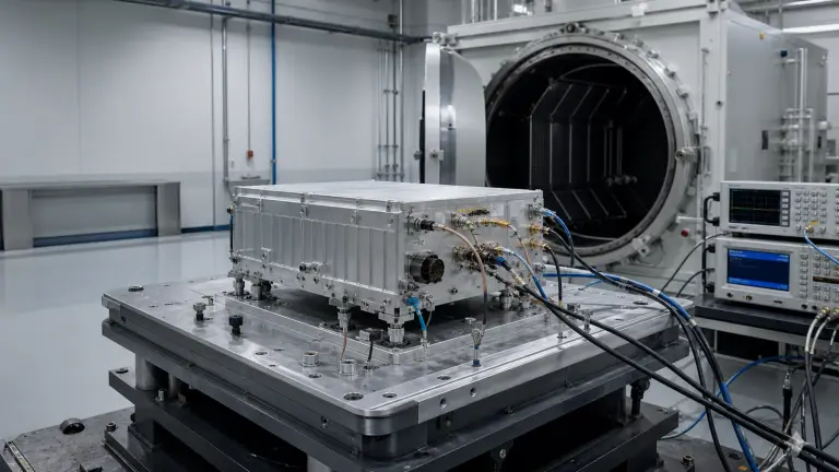
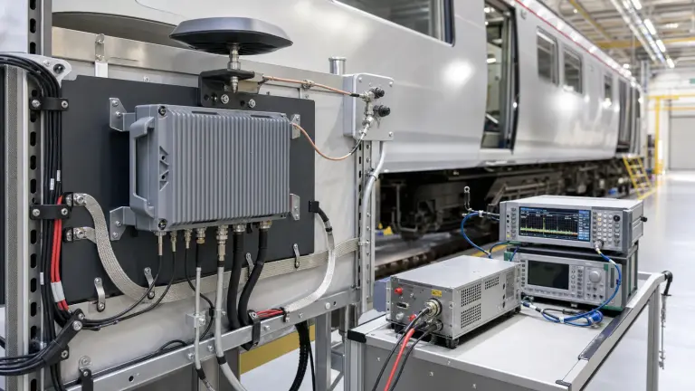
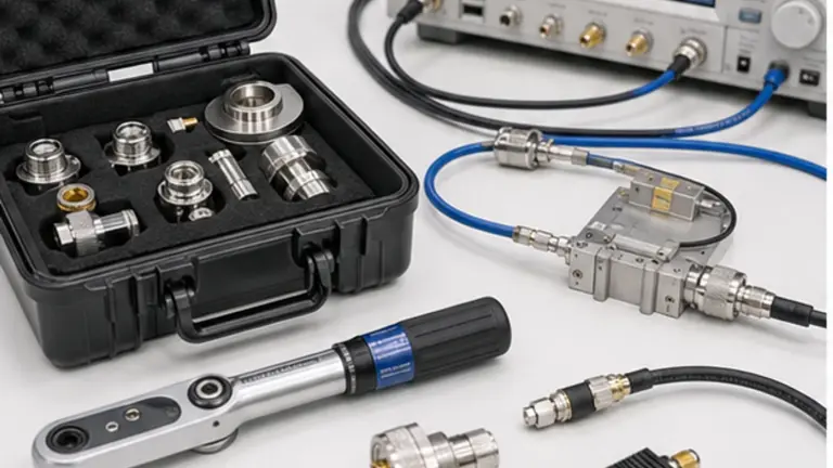
Measure conversion gain or loss, match, noise and linearity across a matrix of RF, LO and IF states. Search for image response, LO leakage, harmonics and intermodulation products using the bandwidth and detector settings defined by the project. For modulated signals, verify EVM or spectral quality through the complete conversion path. Repeat critical states over temperature, supply tolerance and switching sequences, and include fixture loss or cable correction at named reference planes.
- RF, LO and IF bands, tuning steps and guard bands
- LO source, drive range, phase-noise and leakage limits
- Conversion gain or loss, flatness and calibration method
- Noise, compression, IP3 and maximum safe input
- Image rejection, sideband suppression and prohibited spurs
- Switching time, phase continuity and control interface
- Supply, connectors, outline and environmental limits
- Acceptance frequency matrix and delivery evidence
Selection and approval boundary
This category organizes conversion and IF-processing families; it does not prove a particular module will meet an unreviewed frequency plan. Model approval requires a project-specific RF, LO and IF matrix plus reproducible spur, dynamic-range and interface evidence.