
LCRF

Privacy preferences

Choose optional purposes independently. You can change or withdraw your choice at any time from the footer.

Strictly necessary

Required for security, session functions and storing your privacy choice.

Always active
Preferences

Remembers optional display or language settings when these features are enabled.

Analytics

Uses first-party visitor and session identifiers to measure pages, referrals and inquiry interactions.

Marketing

Allows marketing measurement or third-party advertising technologies if they are introduced in the future.

Quantum & Research RF

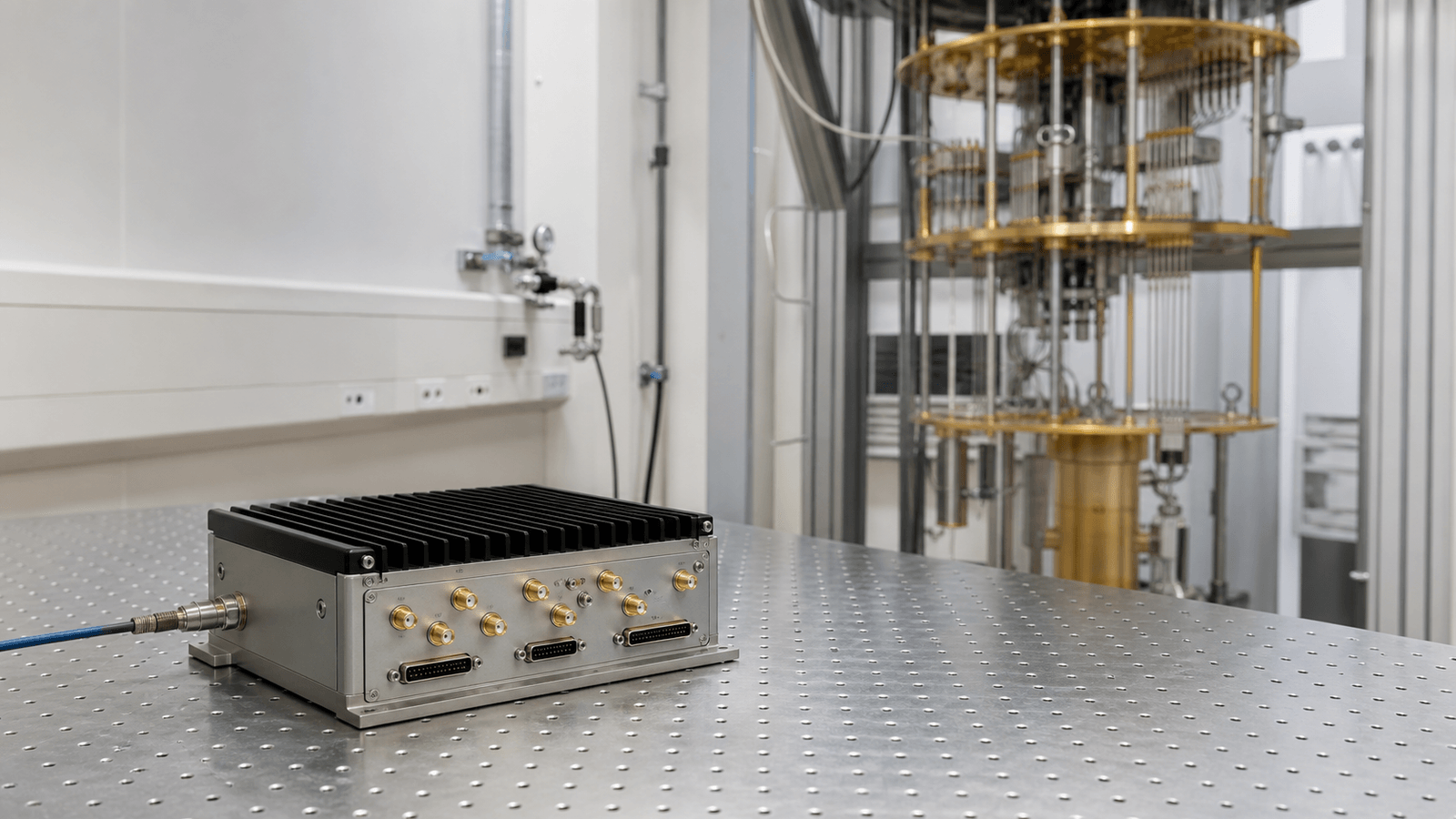
Quantum and research RF covers frequency references, coherent signal generation, low-noise receive paths and controlled RF stimulus used in quantum-control benches, cryogenic readout systems and precision laboratory instruments.

Quantum & Research RF RF application visual

RF paths for precision research systems

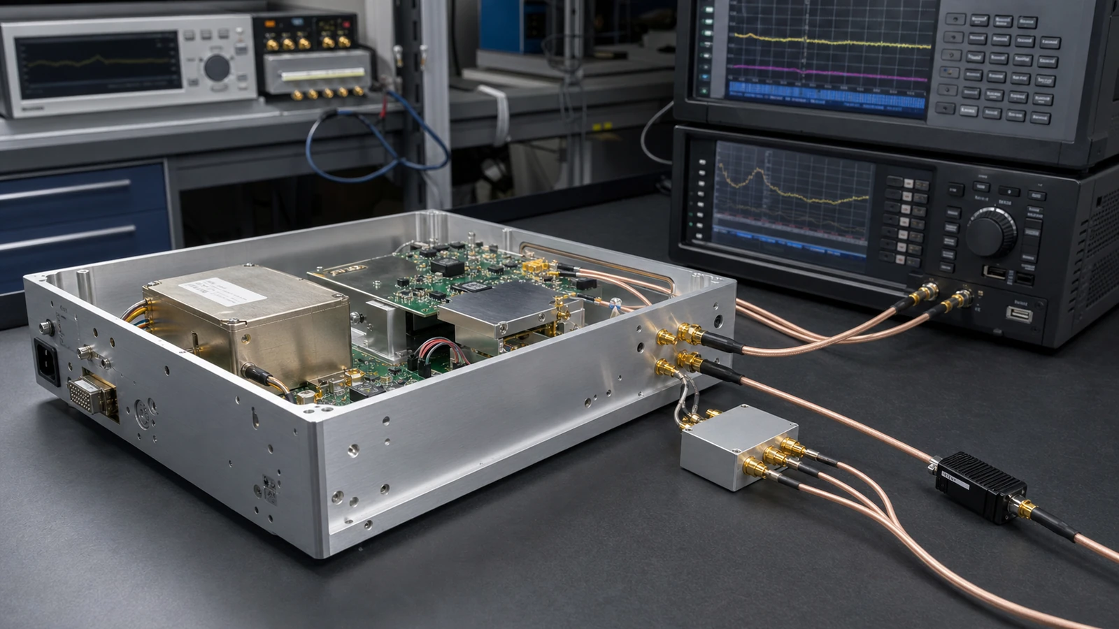
Quantum and research RF work usually starts from stable frequency references and controlled microwave signals. The same rack may combine frequency synthesizers, OCXO references, IQ modulation, low-noise receive gain and low-loss interconnect so a repeatable signal path can be used across control, readout and measurement stages.

Laboratory boundary

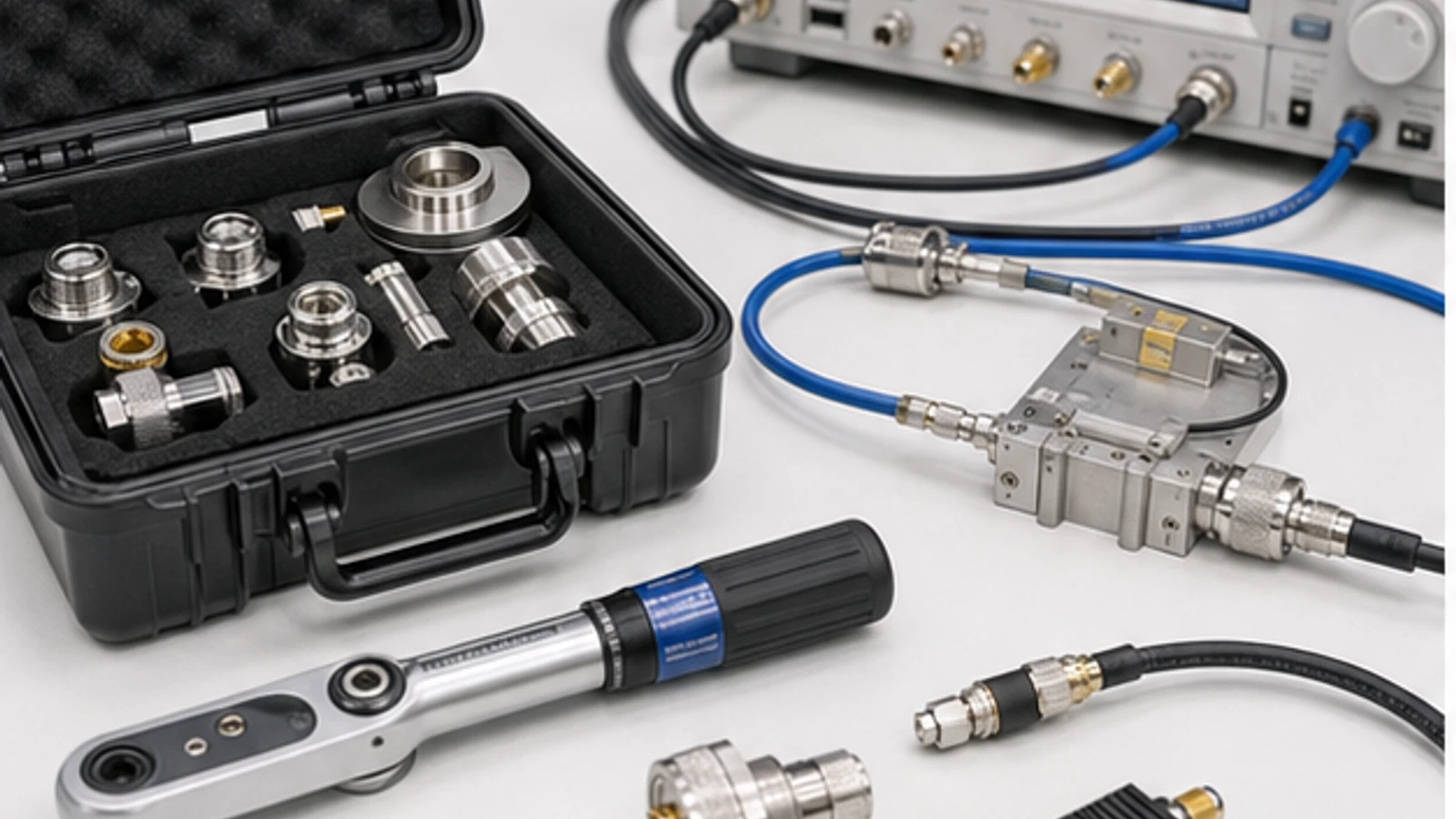
The important boundary is not a single module name, but the relationship between phase noise, frequency stability, output level, cable loss, receive sensitivity and the measurement fixture. In low-temperature or shielded lab setups, connector repeatability, reference distribution and path loss often affect the final data as much as the RF block itself.
Articles

FAQ

Does sharing a frequency reference make multiple RF sources phase coherent?

A shared reference aligns average frequency, but deterministic relative phase also depends on trigger timing, divider state, path delay, retune behavior, relock and restart conditions.

What is an RF measurement reference plane, and when is fixture de-embedding required?

The measurement reference plane is the electrical boundary where a corrected value is claimed; de-embedding is needed only when a characterized fixture network must be removed to report at a different DUT plane.

When should an RF source use phase-noise spot limits versus integrated jitter?

Use phase-noise spot or mask limits when offset regions drive RF behavior; use integrated jitter only when the project defines the integration band and a time-domain error budget.

Engineering inquiry

Share your RF requirement

Share the product, operating requirements and project context. Our engineering team will route your request to the right specialist.

AttachmentsAttach drawings, BOMs, specifications or test files. Up to 5 files, 10 MB each and 25 MB total.
or drag and dropPDF, DOCX, XLSX, CSV, TXT, JPG, PNG, S1P and S2P
Typically reviewed within one business dayProject information is handled confidentially