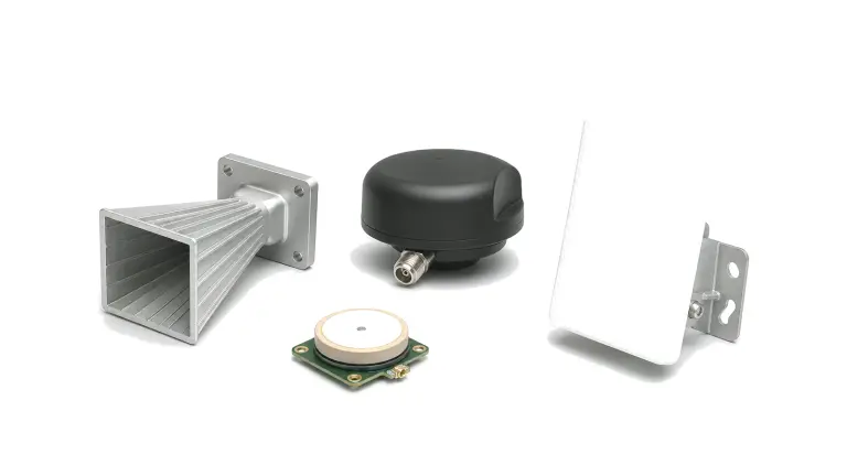
What RF hardware is required for radar and RF sensing?
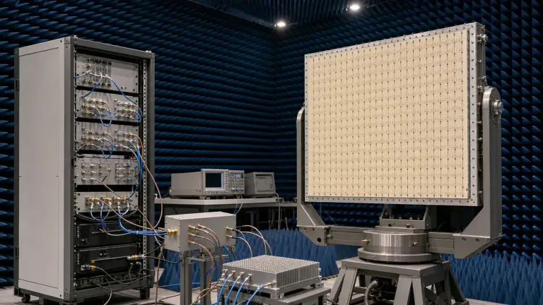
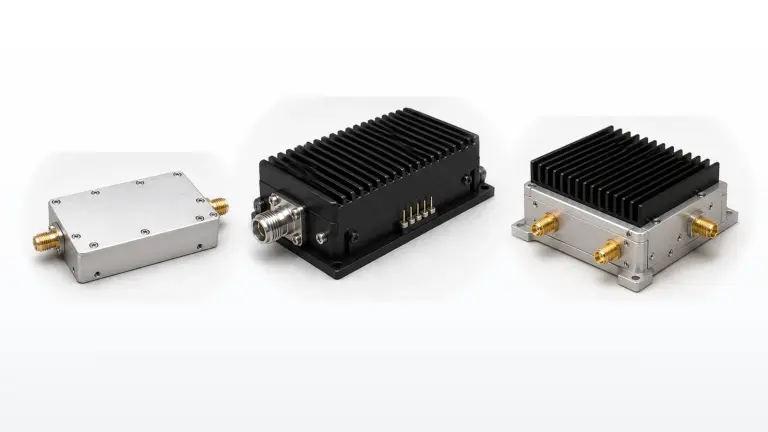
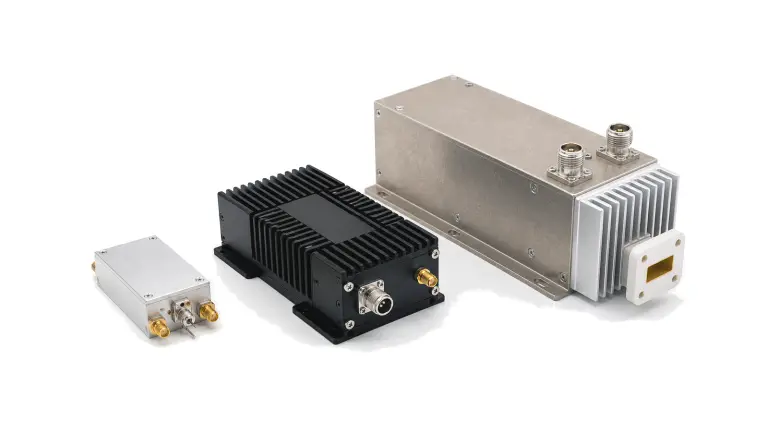
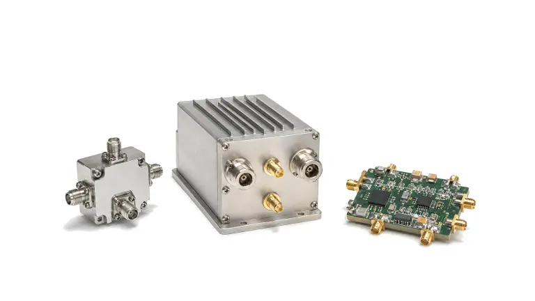
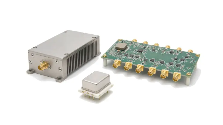
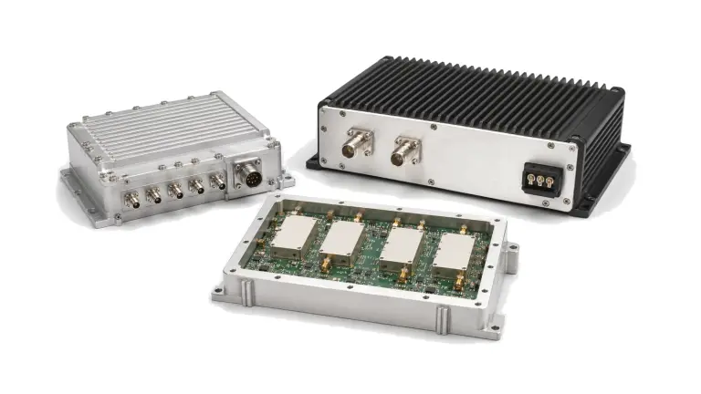
A radar or RF sensing path typically combines a coherent source and timing reference, waveform generation or conversion, transmit gain and power, switching or duplexing, antenna feeds, protected low-noise receive gain, filtering, detection or digitization interfaces and monitoring points. The arrangement changes with surveillance, phased-array, automotive, weather, imaging or material-sensing use. Range, resolution, update rate, target environment and operating duty cycle set the hardware requirements.
How is a radar RF signal chain designed?
Start with the sensing task and waveform. Define range, velocity or material response to be detected, frequency band, bandwidth, pulse or chirp format, repetition rate, coherent processing interval and antenna coverage. Build the transmit and receive paths around the same reference planes so that output energy, feed loss, leakage, receiver recovery and noise can be evaluated together. In multi-channel systems, include phase and amplitude alignment, reference distribution and channel-to-channel isolation from the beginning.
| Radar path | Design focus | Evidence to retain |
|---|---|---|
| Source and timing | Frequency accuracy, phase noise, coherence and trigger alignment | Reference architecture, lock time, jitter or phase-noise data and synchronization states |
| Transmit chain | Peak and average power, pulse fidelity, modulation quality and thermal load | Waveform-specific output, droop, rise or fall time, harmonics and duty-cycle data |
| Antenna and switching | Coverage, loss, isolation, switching time and reflected power | Port maps, feed loss, beam states, recovery timing and mismatch limits |
| Receive chain | Noise, gain, dynamic range, leakage recovery and blockers | Noise figure, compression, linearity, settling and gain or phase alignment |
Which RF specifications matter for radar and sensing hardware selection?
Frequency and instantaneous bandwidth determine range resolution and component coverage, while waveform and duty cycle determine peak stress and average thermal load. Transmit output must be stated with pulse width, repetition rate, droop and spectral limits. Receiver noise, gain, dynamic range, recovery time and strong-signal tolerance must include transmit leakage and nearby emitters. Phase noise, timing jitter, channel balance and switching latency become critical in coherent or array systems.
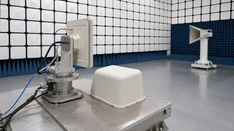
Mechanical and environmental conditions can change RF behavior. Antenna placement, cable phase stability, vibration, temperature gradients, cooling, radome or enclosure effects and service access belong in the architecture review. For safety or mission-critical use, define fault monitoring, inhibit behavior and configuration control as verifiable interfaces.
How do you test and verify radar and RF sensing hardware?
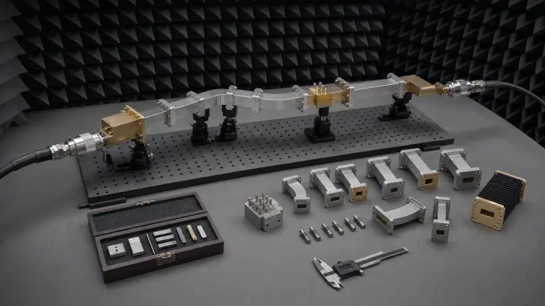
Test the source, transmit, switching, antenna-feed and receive paths separately, then verify them as one timed system. Use the project pulse, chirp or modulated waveform to measure output, spectral behavior, pulse fidelity and thermal stability. Characterize receive noise and dynamic range, inject representative leakage or blockers, and measure recovery before the earliest valid echo. Multi-channel systems require amplitude, phase and timing calibration across frequency, temperature and operating state.
- Sensing task, range, resolution, update rate and coverage
- Frequency band, bandwidth, waveform and coherent timing
- Peak and average transmit power with duty cycle
- Antenna, feed, switching and isolation architecture
- Receive noise, dynamic range, recovery and blocker limits
- Channel count, phase or amplitude alignment and calibration
- Environmental, cooling, protection and monitoring requirements
- Qualification and per-unit acceptance evidence
Architecture and approval boundary
Radar and sensing RF requirements must be defined at system level; detection performance cannot be claimed for an unspecified platform. Final hardware approval requires project waveform, antenna, timing, target-environment and acceptance evidence.