
LCRF

Privacy preferences

Choose optional purposes independently. You can change or withdraw your choice at any time from the footer.

Strictly necessary

Required for security, session functions and storing your privacy choice.

Always active
Preferences

Remembers optional display or language settings when these features are enabled.

Analytics

Uses first-party visitor and session identifiers to measure pages, referrals and inquiry interactions.

Marketing

Allows marketing measurement or third-party advertising technologies if they are introduced in the future.

Receiver Front-End Signal Chain

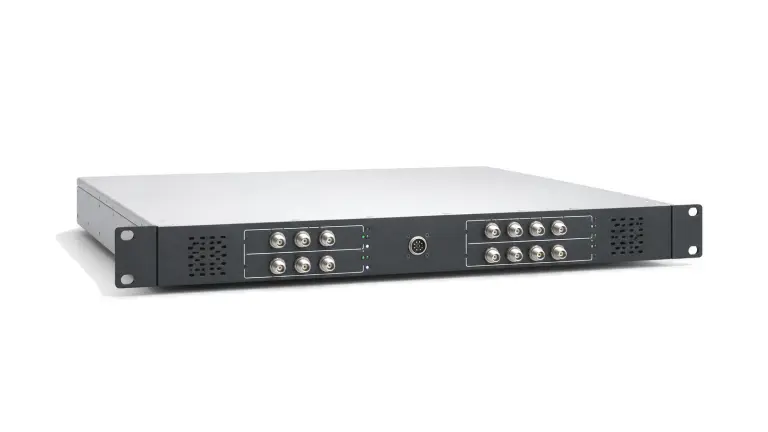
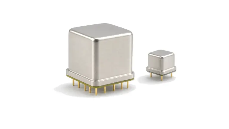
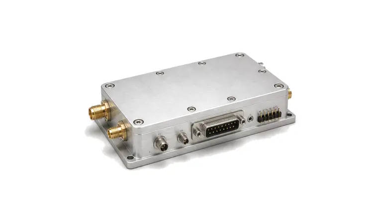
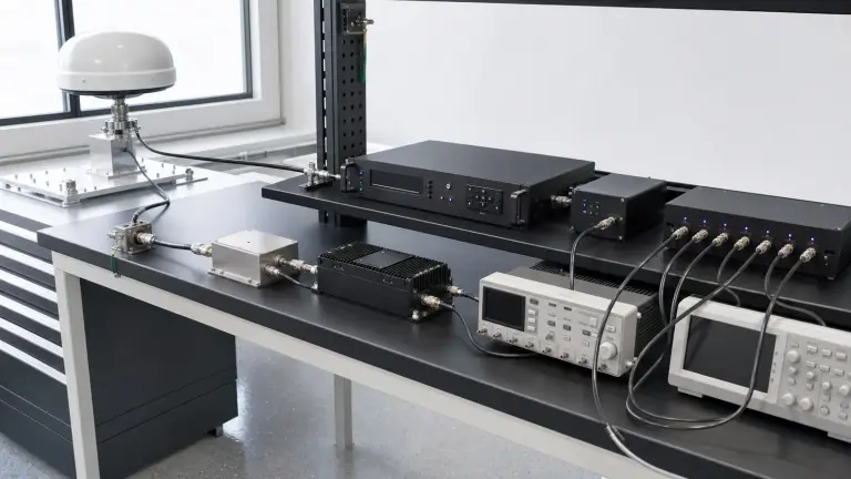
Receiver front-end signal chains connect antenna inputs with filtering, protection, low-noise gain, frequency conversion and monitoring stages while balancing sensitivity, overload margin and interface behavior.

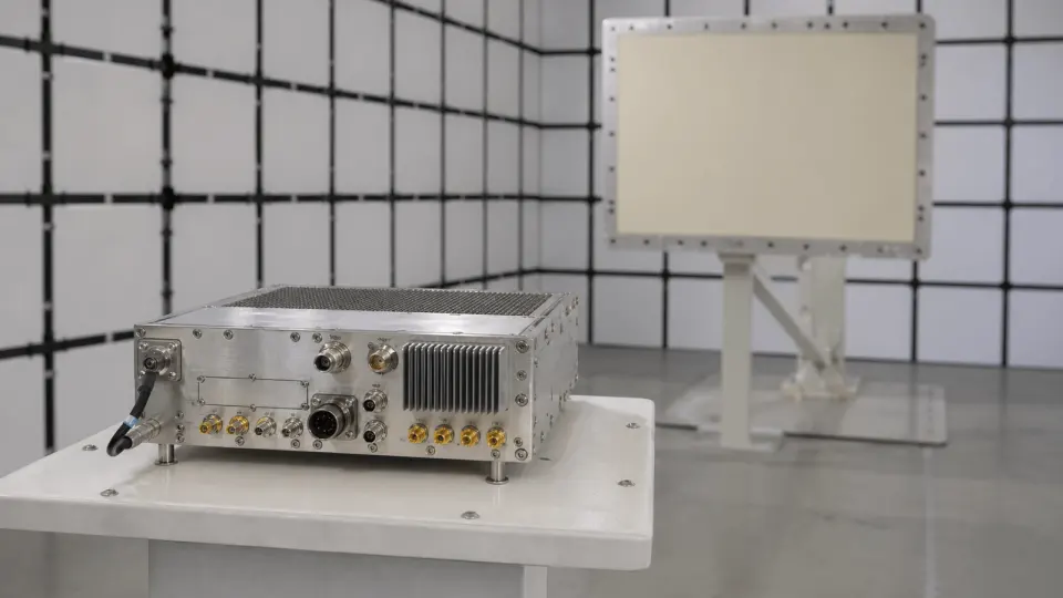
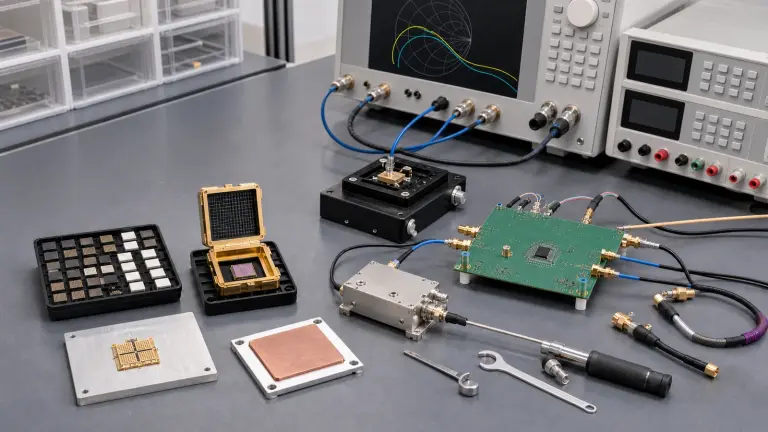
Receiver Front-End Signal Chain RF solution visual

Receiver-chain boundary

A receiver front-end signal chain starts at the antenna input and prepares weak RF signals for conversion, measurement or demodulation. It can include preselection filters, limiter protection, low-noise amplification, mixers, local oscillator references and monitoring points.

System role

The chain is used in surveillance radar, satellite terminals, navigation receivers, monitoring equipment and multi-channel RF platforms where small-signal sensitivity must coexist with blocking signals, nearby transmitters and changing field conditions.

Engineering data

Useful data includes operating band, noise figure, gain distribution, input protection level, linearity, image rejection, conversion plan, local oscillator input, intermediate-frequency output, impedance, connector format and environmental limits.

Start with the service and availability target, not a component list

Receiver Front-End Signal Chain architecture
Freeze the link contract in measurable terms
Receiver Front-End Signal Chain design requirements
Draw the power and signal reference planes before calculating margin
Receiver Front-End Signal Chain integration
Build received power and link margin in one direction at a time
Receiver Front-End Signal Chain test and verification
Turn bandwidth and demodulation performance into a receiver budget

How to Translate a Wireless Link Requirement into an RF Front-End Specification

A link-engineering method for turning service bandwidth, availability, EIRP, propagation, receiver sensitivity, duplexing and waveform quality into RF hardware limits that can be designed and verified.
Wireless Link Budget and RF Front-End Requirements

Articles

FAQ

How should GNSS receiver blocker and interference tolerance be specified?

Define the interferer waveform, frequency, bandwidth, duty cycle, coupling plane, wanted-signal state, exposure and measurable degradation or recovery metric instead of relying on an anti-jam label.

What belongs in a GNSS antenna, LNA, filter and cable RF budget?

Budget antenna gain, pre-LNA loss, LNA noise and gain, filtering, cable loss, active-antenna power, return loss, linearity, receiver range and blocker headroom in physical path order.

How should PPS and 10 MHz timing-distribution delay and skew be verified?

Verify every delivered timing channel at its real load by separating fixed calibrated delay, channel skew, environmental drift, output level, edge or phase behavior and path-dependent uncertainty.

What must an RF semiconductor bias-sequencing and protection specification include?

Define rails, current setting, startup and shutdown order, control defaults, transient limits, fault protection and recovery at the device-side plane.

What does holdover mean in a GNSS-disciplined timing system?

Holdover is the bounded time or frequency performance after GNSS reference loss, defined by the starting state, outage duration, environment, local oscillator, steering history, maximum time error and recovery rule.

How should package, PCB layout and thermal limits be specified for an RF IC or MMIC?

Control the RF launch, exposed pad or flange, grounding, via field, board stack, assembly and heat path, then calculate junction temperature from real dissipation and boundary temperature.

How should S-parameters, reference planes and stability be reviewed for an RF IC or MMIC?

Confirm model conditions and planes, analyze credible source and load states, then verify the intended bias network, board and fixture rather than relying on nominal K alone.

What evidence is needed to handle, assemble and accept bare-die RF MMICs?

Control ESD-safe storage, pickup, attach, bond geometry, inspection, die identity and lot-linked electrical acceptance before releasing a bare-die assembly.

Engineering inquiry

Share your RF requirement

Share the product, operating requirements and project context. Our engineering team will route your request to the right specialist.

AttachmentsAttach drawings, BOMs, specifications or test files. Up to 5 files, 10 MB each and 25 MB total.
or drag and dropPDF, DOCX, XLSX, CSV, TXT, JPG, PNG, S1P and S2P
Typically reviewed within one business dayProject information is handled confidentially