
How should RF filters, duplexers and spectrum-selection hardware be selected?
Specify an RF filter or duplexer as a multi-condition S-parameter and power contract at named connector reference planes. Define the usable passband, continuous transition and stopband masks, worst-case insertion and return loss, phase or group-delay limits, every duplexer port state, and CW or pulsed power with temperature and cooling conditions. Acceptance must use calibrated VNA reference planes and, where power matters, a separate thermal and nonlinear test; one center-frequency loss value or one isolation point is not enough. A field-ready method for turning channel plans, blockers, waveform limits, shared-antenna states and thermal conditions into an RF filter or duplexer specification that can be measured and accepted. Filters, duplexers and spectrum-selection hardware define which RF or microwave frequencies pass, are rejected or share antenna paths. This range includes bandpass, low-pass, high-pass, notch, cavity, ceramic, waveguide, SAW/BAW and multi-port assemblies.
Commercial and engineering decisions covered
- Filters, Duplexers & Spectrum Selection supplier: evaluate whether the supplier can support the required topology, interfaces, data and change control
- Filters, Duplexers & Spectrum Selection manufacturer: separate manufacturing evidence and repeatability from a single typical sample
- Filters, Duplexers & Spectrum Selection technical specifications: turn channel masks, ports, loss, rejection, delay, power and environment into measurable limits
- Filters, Duplexers & Spectrum Selection selection guide: choose topology and technology from the signal plan rather than a center-frequency label
- Filters, Duplexers & Spectrum Selection test and verification: verify small-signal, power, thermal and multi-port behavior at named reference planes
Choose the topology from the spectrum task
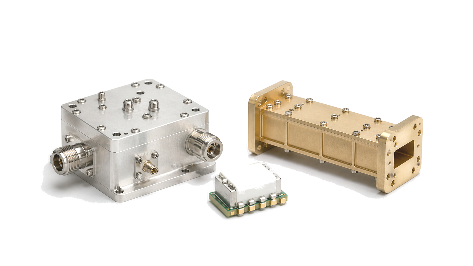
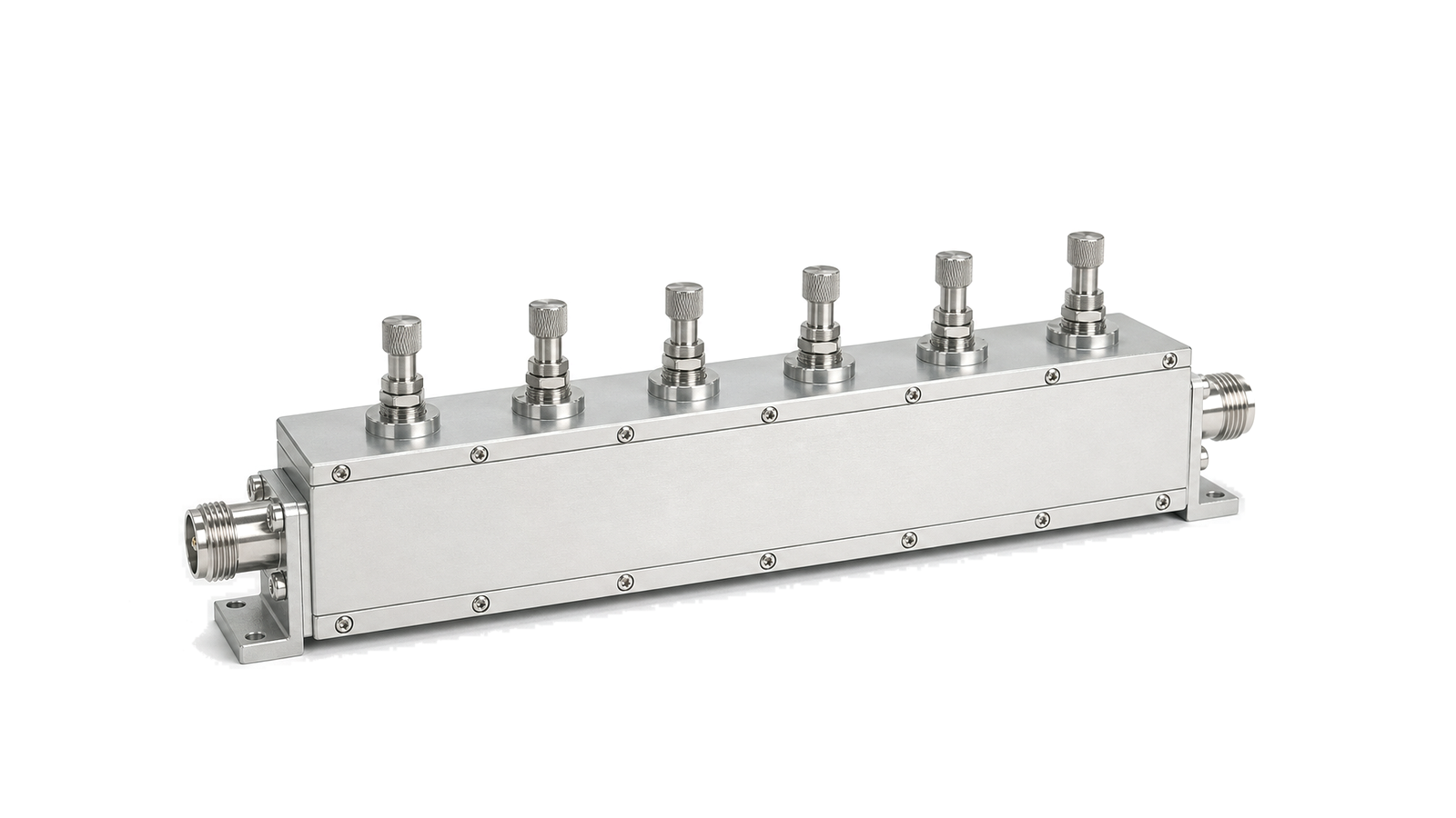
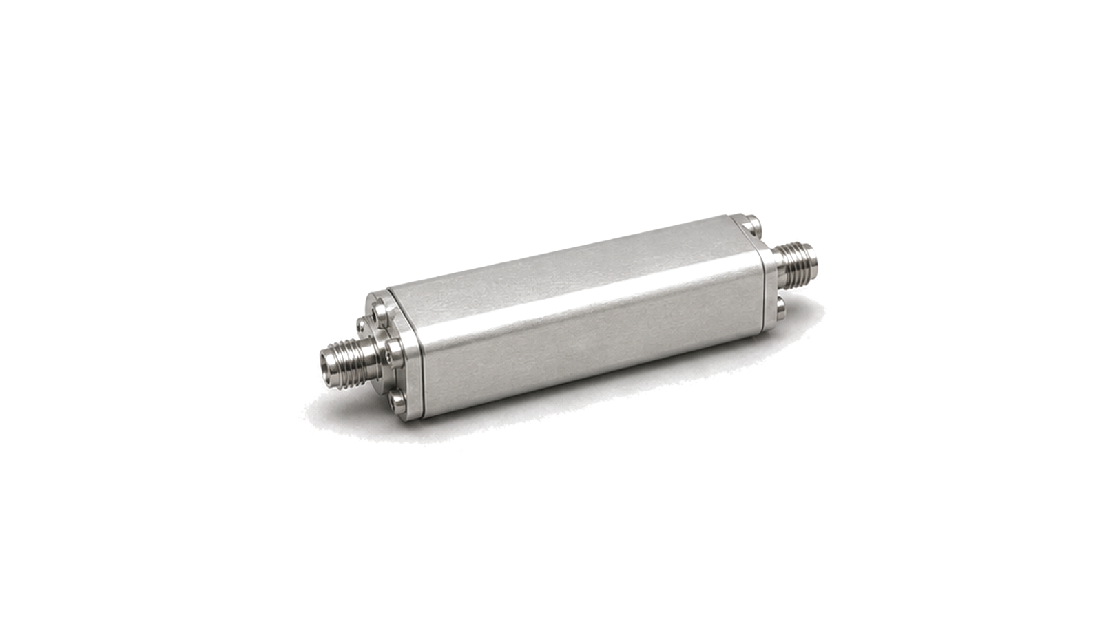
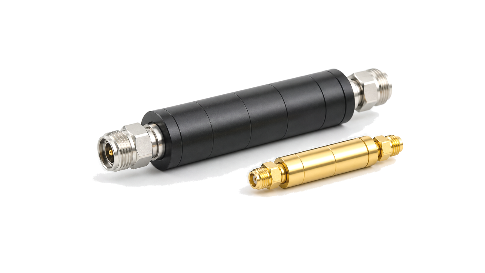
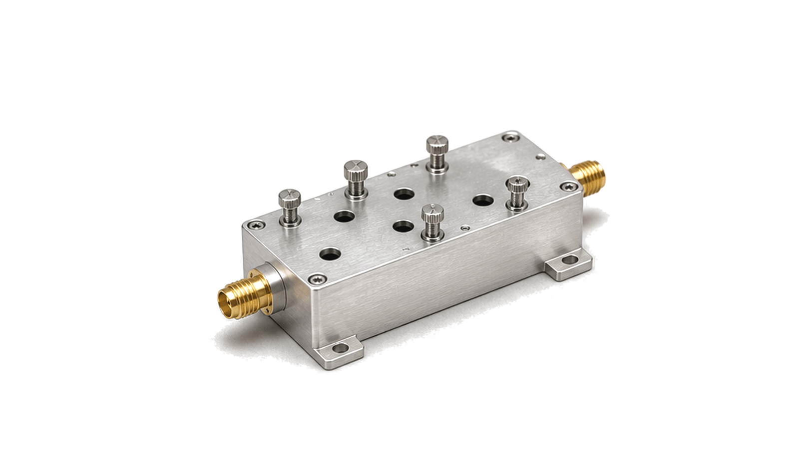
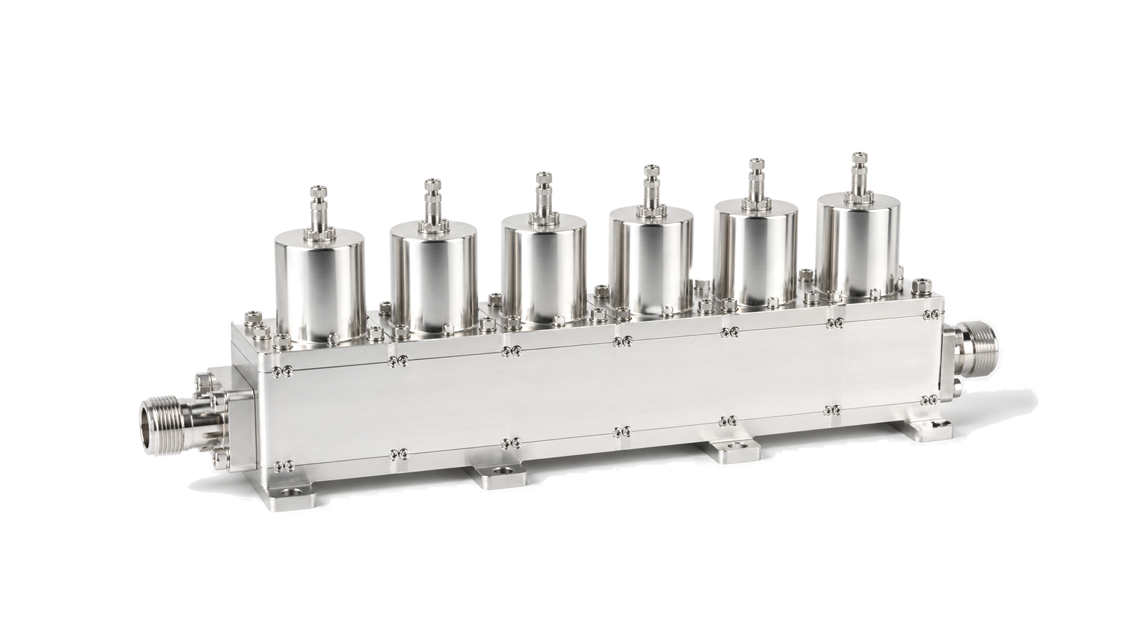
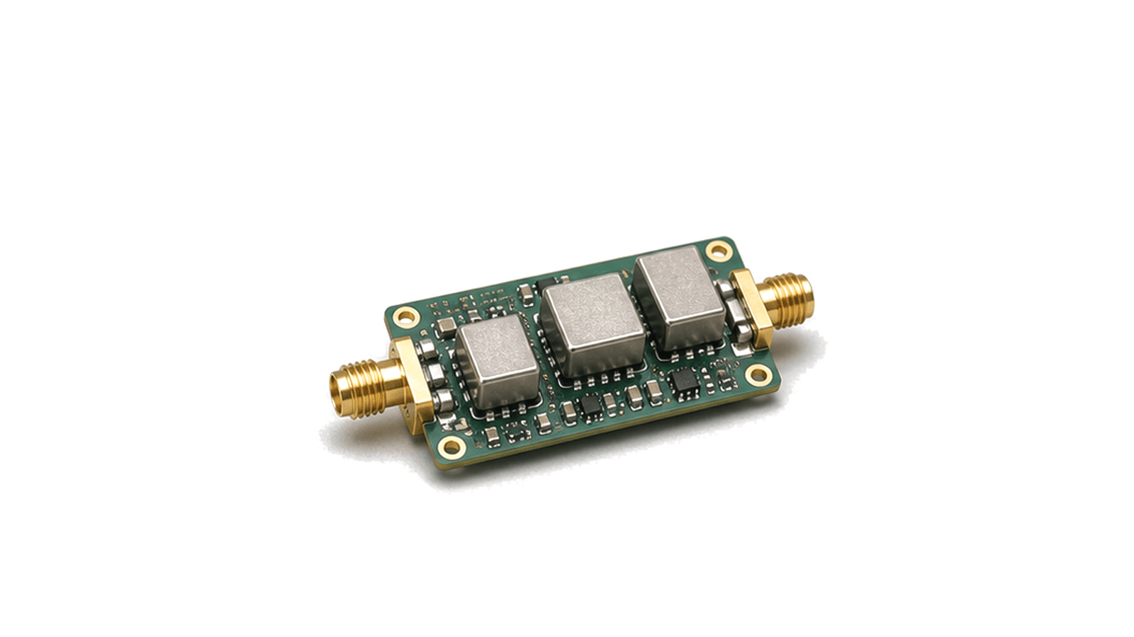
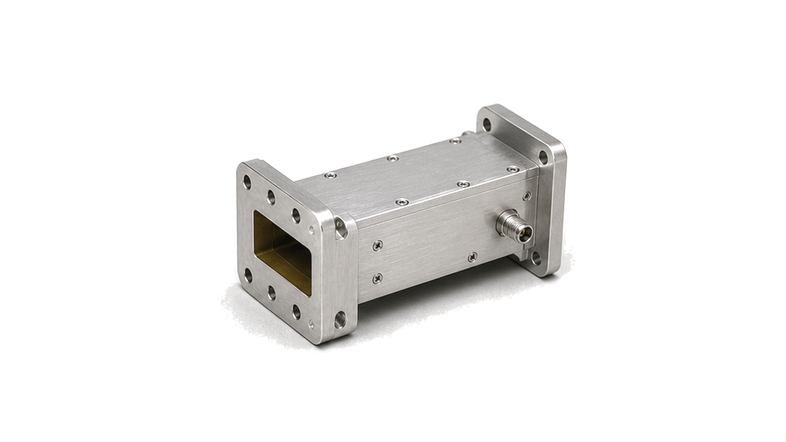
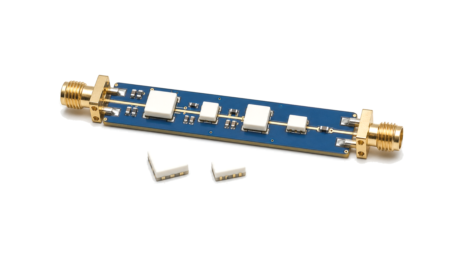
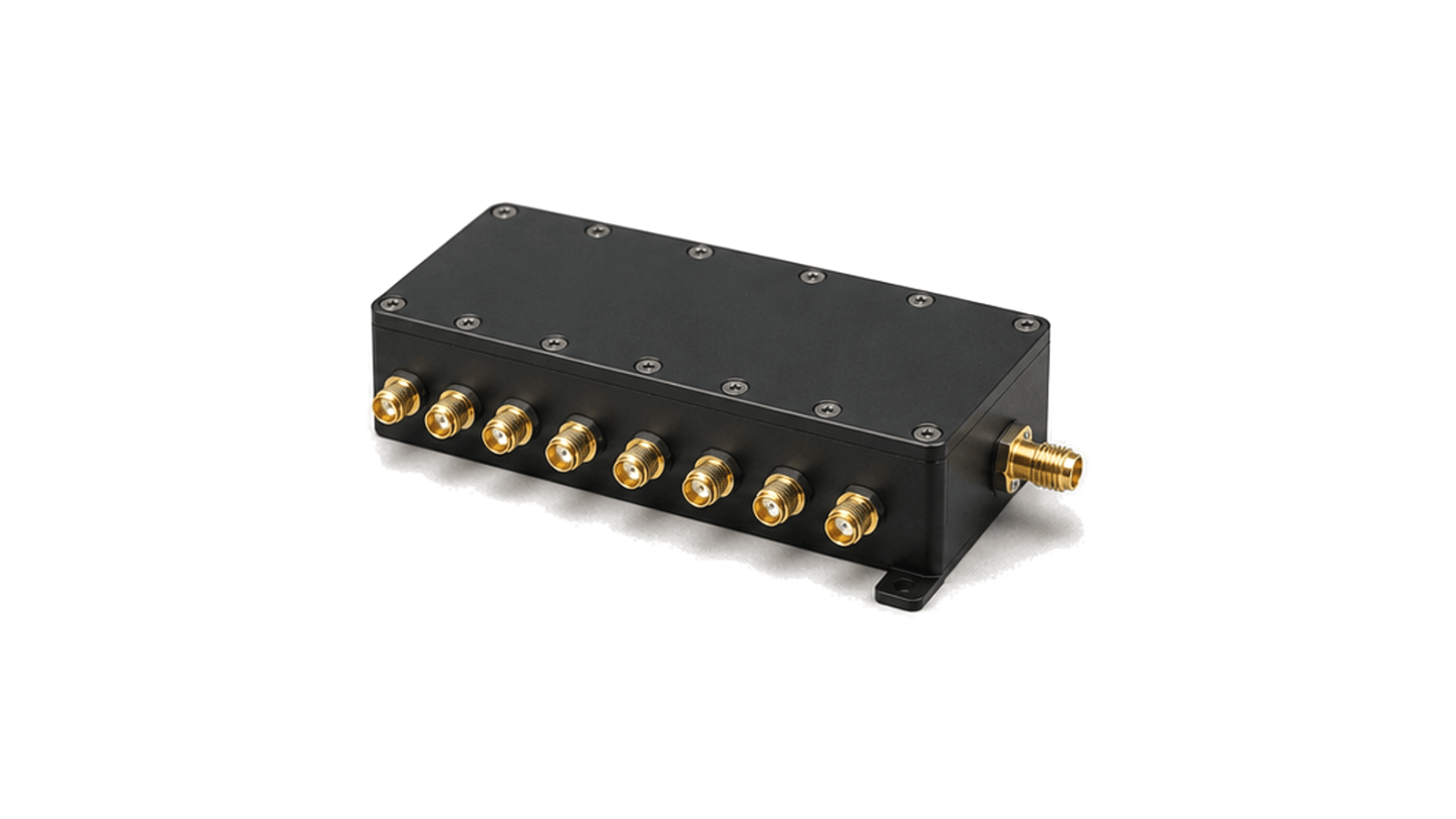
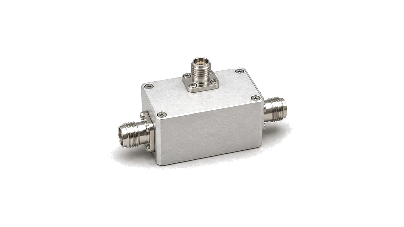
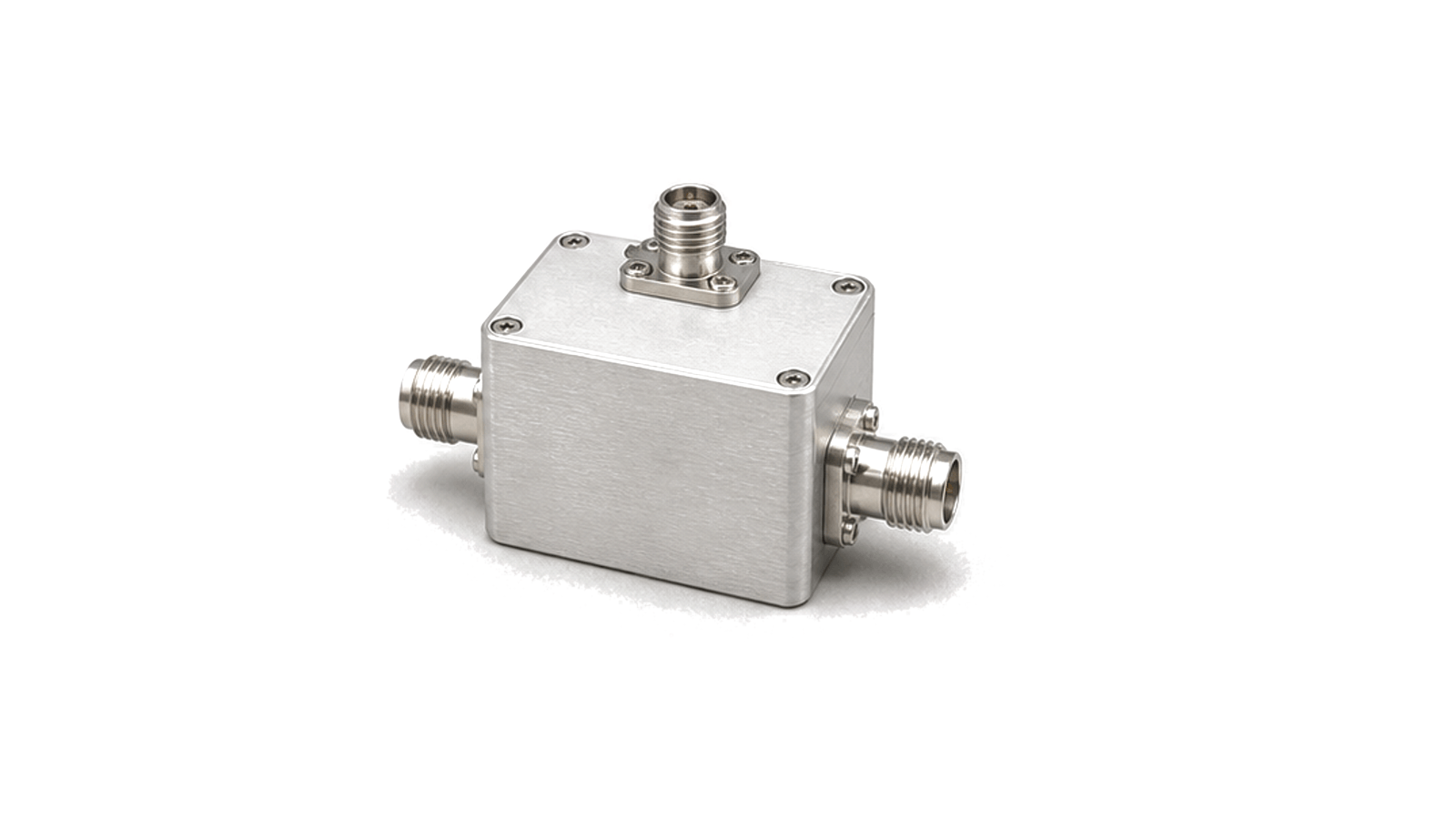
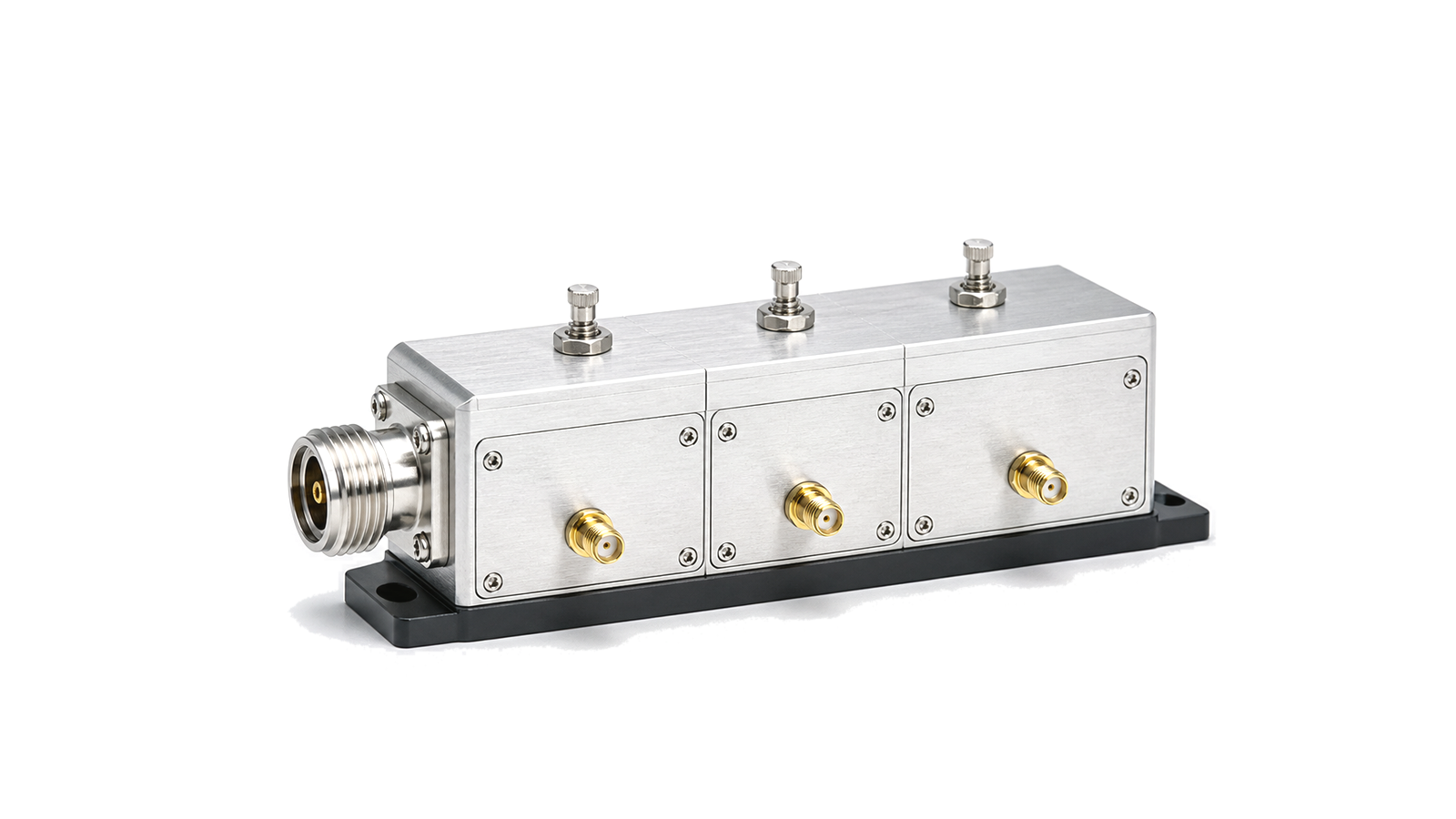
Use band-pass filters to preserve one operating band, low-pass or high-pass filters to control one side of the spectrum, and band-stop or notch filters to suppress a known interferer. Cavity and waveguide structures suit low loss, steep rejection or higher power when size permits; ceramic and SAW/BAW technologies trade size, bandwidth, loss, delay and power differently. A diplexer separates two bands, a duplexer coordinates transmit and receive paths, and a triplexer or switched bank manages more states. Port count, simultaneous operation, isolation path and failure state must be stated before comparing families.
Convert the channel plan into a measurable contract
Define the usable passband rather than a nominal center alone, then provide continuous transition and stopband masks with worst-case insertion loss, return loss, rejection, ripple, phase or group-delay limits. For shared-antenna assemblies, specify every driven, terminated and measured port combination and the reference impedance. Power requires waveform, peak and average level, duty cycle, mismatch, temperature, cooling and duration. Add connector or flange, mounting, tuning, sealing and environmental limits so electrical evidence belongs to the delivered configuration.
Qualify supplier and manufacturing evidence
Ask which revision, lot, fixture, calibration, temperature and power condition produced each curve. Guaranteed limits, test coverage, tuning method, acceptance data, process controls, source traceability and notification of material or geometry changes matter more than an isolated typical trace. For a custom assembly, freeze channel plan, mechanical envelope, interface drawing, plating, resonator or substrate technology and adjustment rules. Production correlation should use known standards and stable reference planes, with a disposition process for retuned, repaired or substituted units.
Verify small-signal and power behavior separately
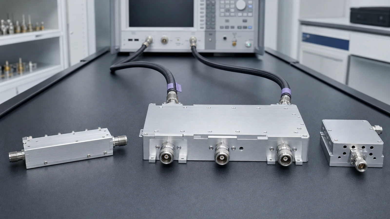
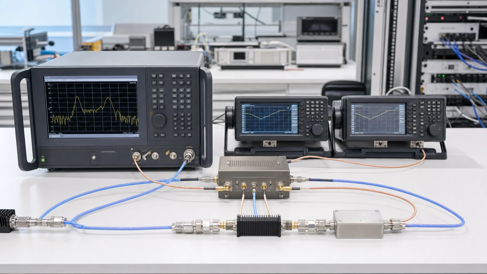
Calibrate the VNA to the declared connector or flange planes and measure all relevant S-parameters over passband, transition and stopband at the required temperature states. Confirm isolation with the unused ports terminated as specified. Group delay and phase need adequate frequency resolution and stable cables. Power verification checks thermal equilibrium, insertion-loss heating, compression, passive intermodulation or other nonlinear products where relevant, and recovery after pulses or mismatch. The report preserves fixture, adapters, calibration, uncertainty, software, serial identity and raw traces.
Filter and duplexer decision matrix
| System need | Likely path | Evidence to compare |
|---|---|---|
| Select one band | Band-pass, low-pass or high-pass filter | Continuous pass/stop masks, loss, match and delay |
| Reject one blocker | Notch or band-stop filter | Notch depth and width, drift, wanted-band loss and power |
| Share an antenna | Diplexer, duplexer or triplexer | All port states, isolation, return loss and simultaneous power |
| Handle high power | Cavity, coaxial or waveguide structure | Peak/average power, heating, mismatch and nonlinear response |
| Reconfigure bands | Switched filter bank | State coverage, switching transient, isolation and default state |
RFQ inputs
- Passband, guard band, transition and stopband masks
- Insertion loss, return loss, ripple, rejection and isolation limits
- Phase linearity or group-delay variation
- Port map, impedance, terminations and simultaneous states
- CW, pulse or modulated power with duty cycle and mismatch
- Connector or flange, envelope, mass, mounting and tuning
- Temperature, cooling, sealing, vibration and other applicable environment
- Calibration planes, uncertainty, sweep settings and acceptance method
- Prototype and production quantity, test data and traceability
- Change notification, repair, retuning and substitution rules
Evidence boundary
A family relationship identifies plausible topologies; it does not prove that a particular unit meets a channel mask, isolation, delay, power or environmental limit. Approval requires configuration-specific guaranteed data and calibrated acceptance evidence at the agreed ports and operating conditions.