Directional RF paths between fixed sites
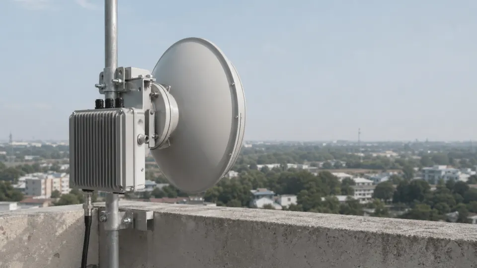
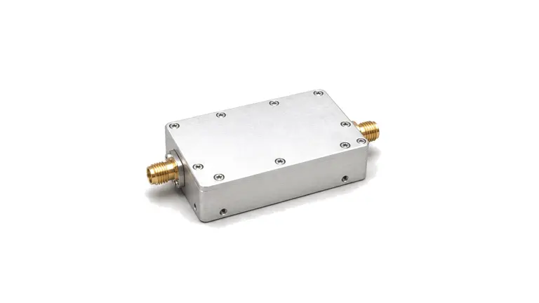
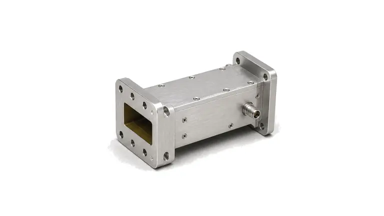
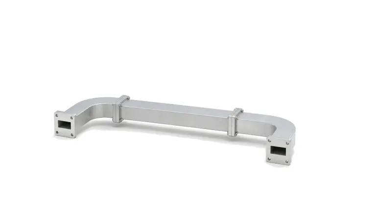
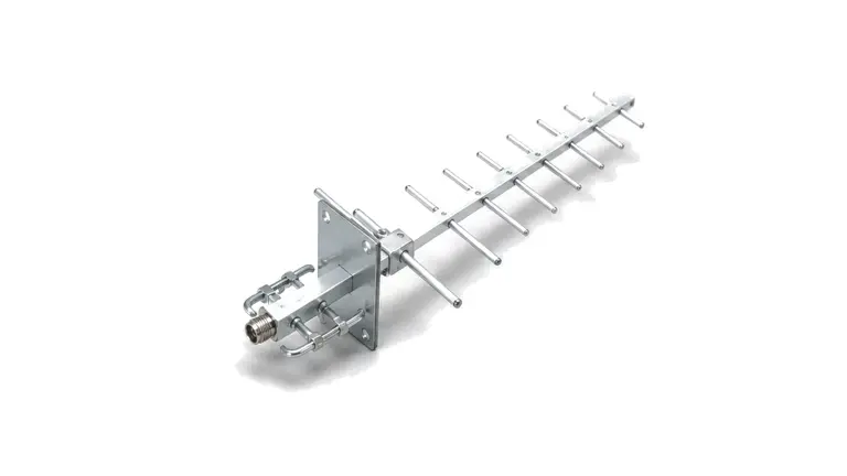
Microwave backhaul and point-to-point links carry communication traffic through narrow, aligned RF paths between towers, rooftops, base stations, remote facilities or private network sites. The chain often combines frequency converters, low-noise receive stages, power amplifiers, waveguide filters, waveguide assemblies and directional antennas.
Link engineering context
The practical boundary is set by channel plan, transmit level, receiver sensitivity, antenna gain, polarization, path loss, fade margin, alignment tolerance, outdoor protection and cable or waveguide loss. These values determine whether the radio path remains stable under weather, site movement, installation length and maintenance conditions.
Define the installed radiation requirement before comparing antennas
- RF hardware for Microwave Backhaul & Point-to-Point Links
- Begin with spatial coverage and an installed coordinate system Write the service volume in azimuth and elevation before naming an antenna type. A point-to-point link may need a narrow main beam and controlled sidelobes; a mobile platform may need coverage through a large elevation range; a navigation receiver may need an upper-hemisphere pattern while rejecting low-elevation inter...
- Microwave Backhaul & Point-to-Point Links RF requirements
- Make the platform, radome and nearby structures part of the antenna configuration Ground plane size, mast, vehicle roof, fuselage, enclosure, cable routing, fasteners and nearby conductive equipment can alter match, pattern, efficiency, phase center and cross-polarization....
- Microwave Backhaul & Point-to-Point Links RF architecture
- Freeze continuous band coverage and the conducted reference plane List every transmit and receive range, guard band and operating state as continuous intervals. A nominal center frequency does not reveal a notch, split band or scan-state limitation....
- Microwave Backhaul & Point-to-Point Links RF hardware selection
- Make the platform, radome and nearby structures part of the antenna configuration Ground plane size, mast, vehicle roof, fuselage, enclosure, cable routing, fasteners and nearby conductive equipment can alter match, pattern, efficiency, phase center and cross-polarization....
- Microwave Backhaul & Point-to-Point Links RF testing and verification
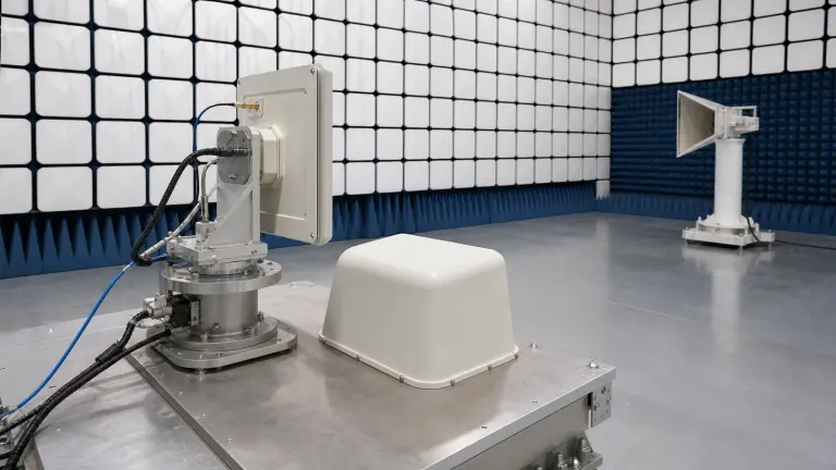
- Design the measurement and evidence package before purchase Conducted tests can establish port match, isolation and feed-network behavior, but radiated gain and pattern require an over-the-air method. State whether substitution gain, comparison gain, near-field transformation, compact-range or far-field measurement is acceptable....
How to Select an RF Antenna: Frequency, Gain, Pattern, Polarization, Match, Power and Installation
A practical antenna-selection method that turns operating band, angular coverage, gain pattern, polarization, port match, waveform power, mounting environment and measurement evidence into an RFQ and acceptance plan.