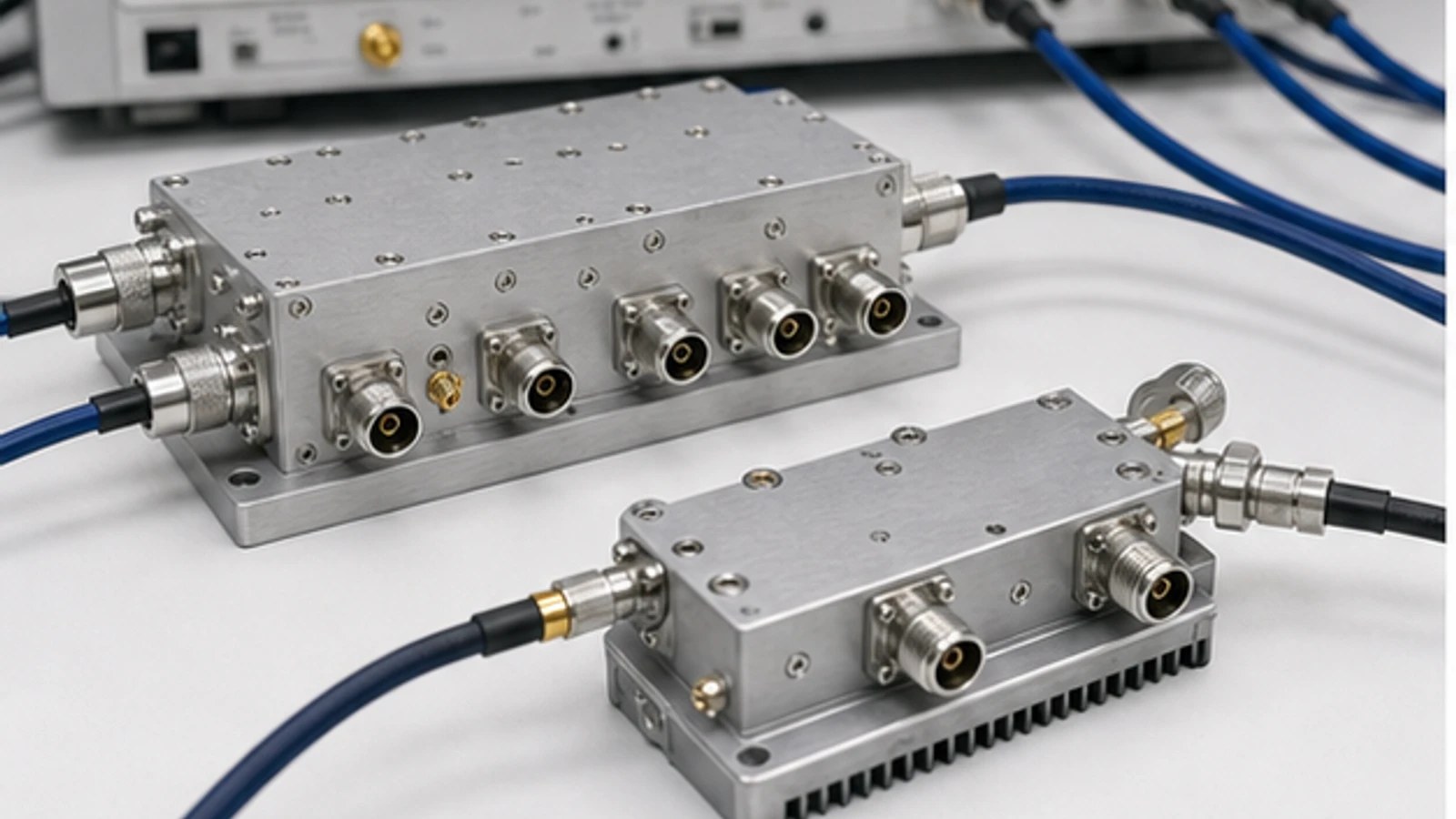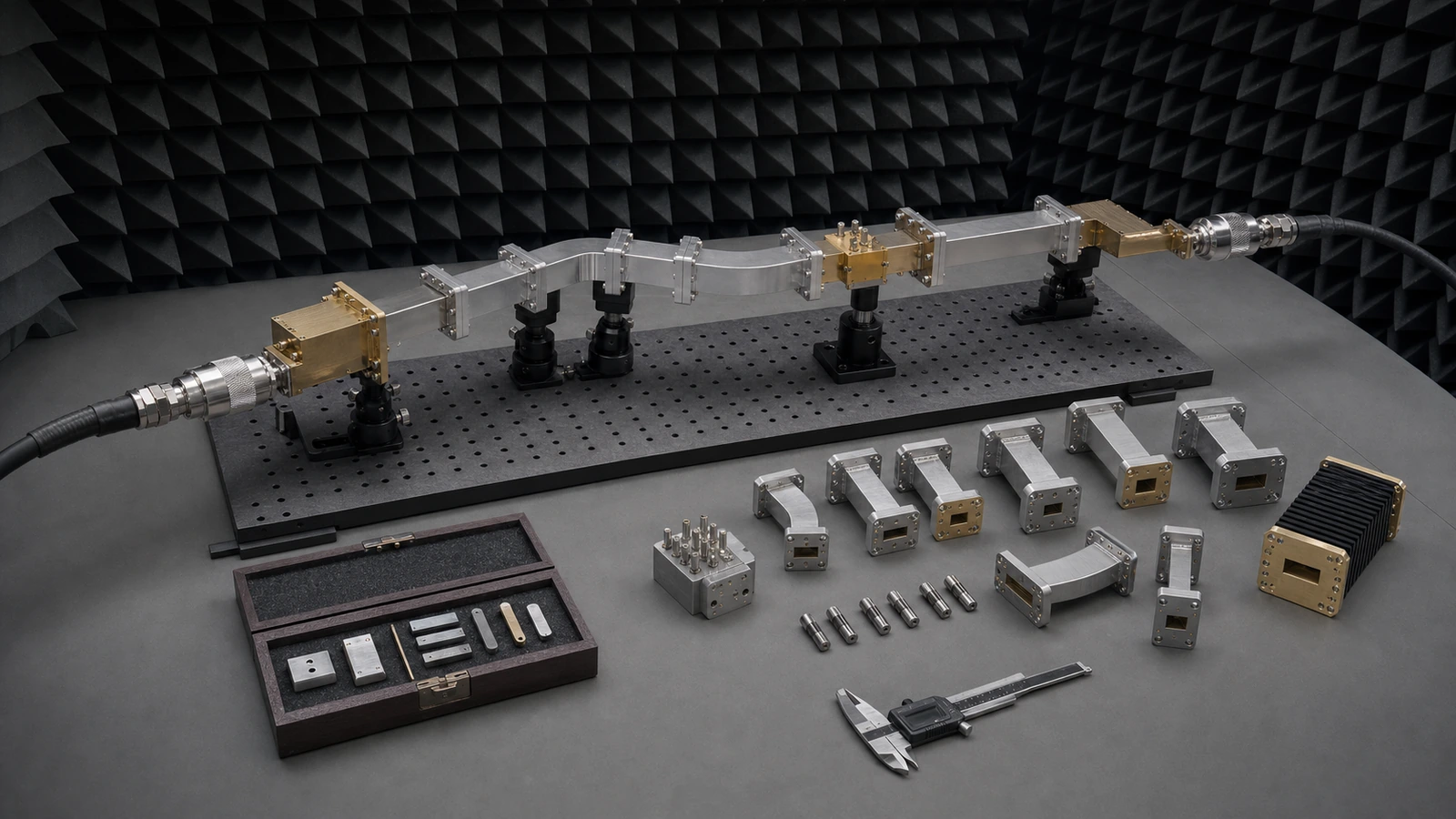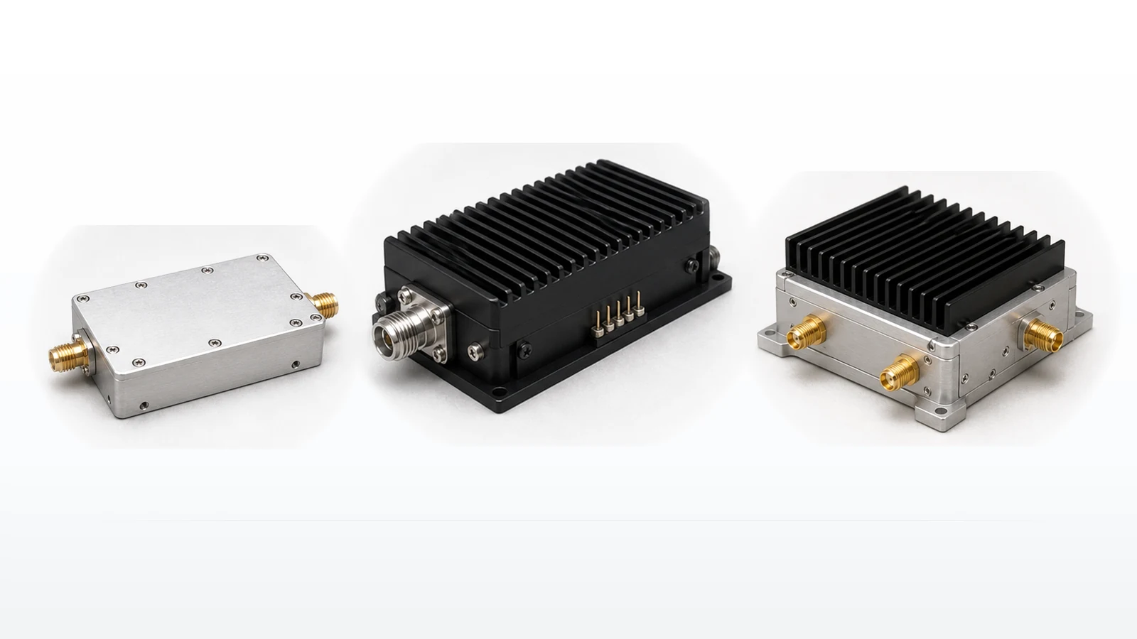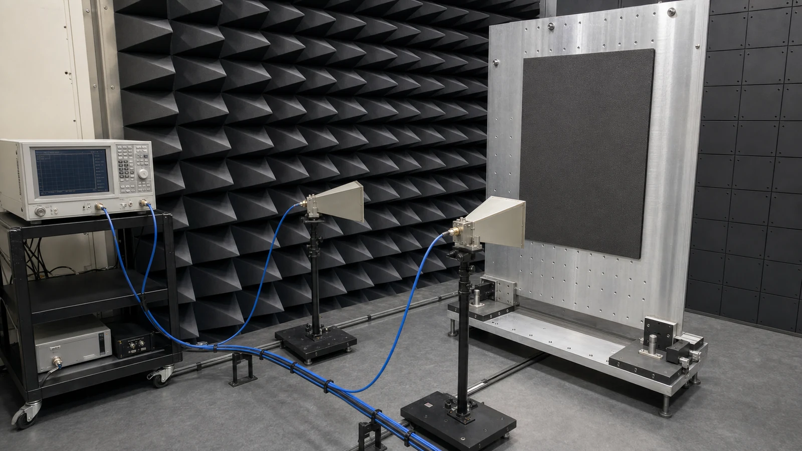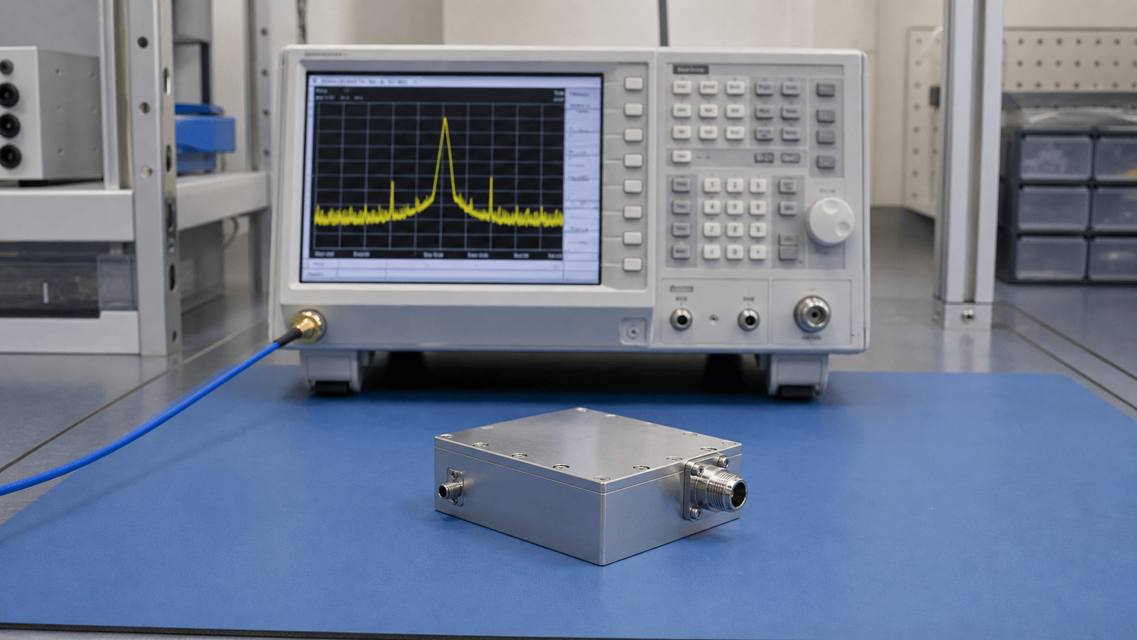
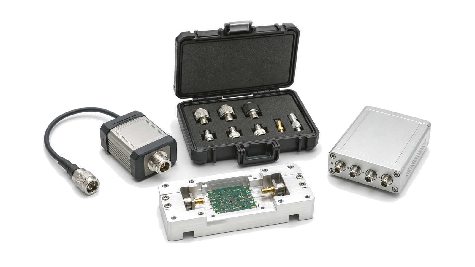
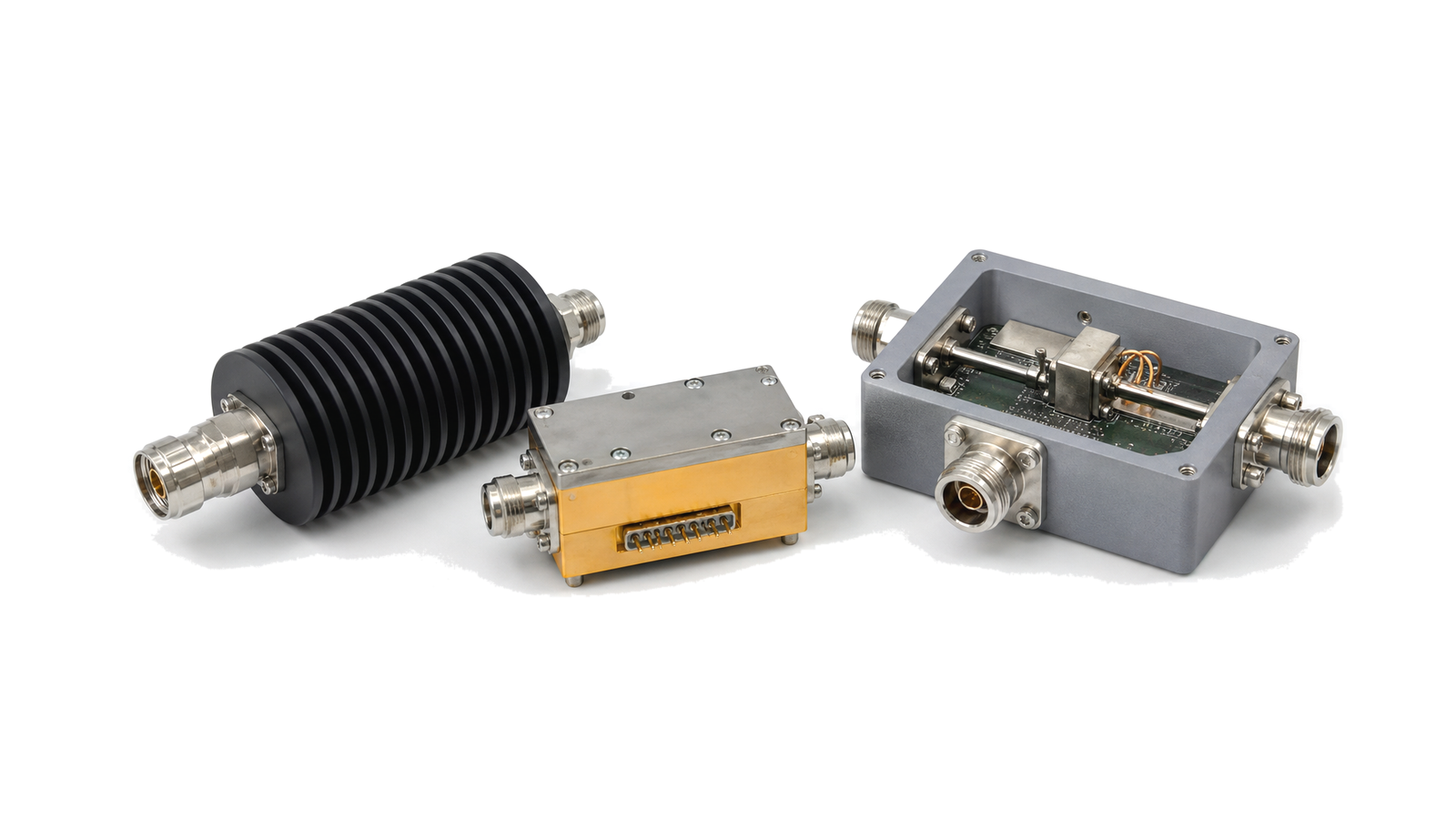
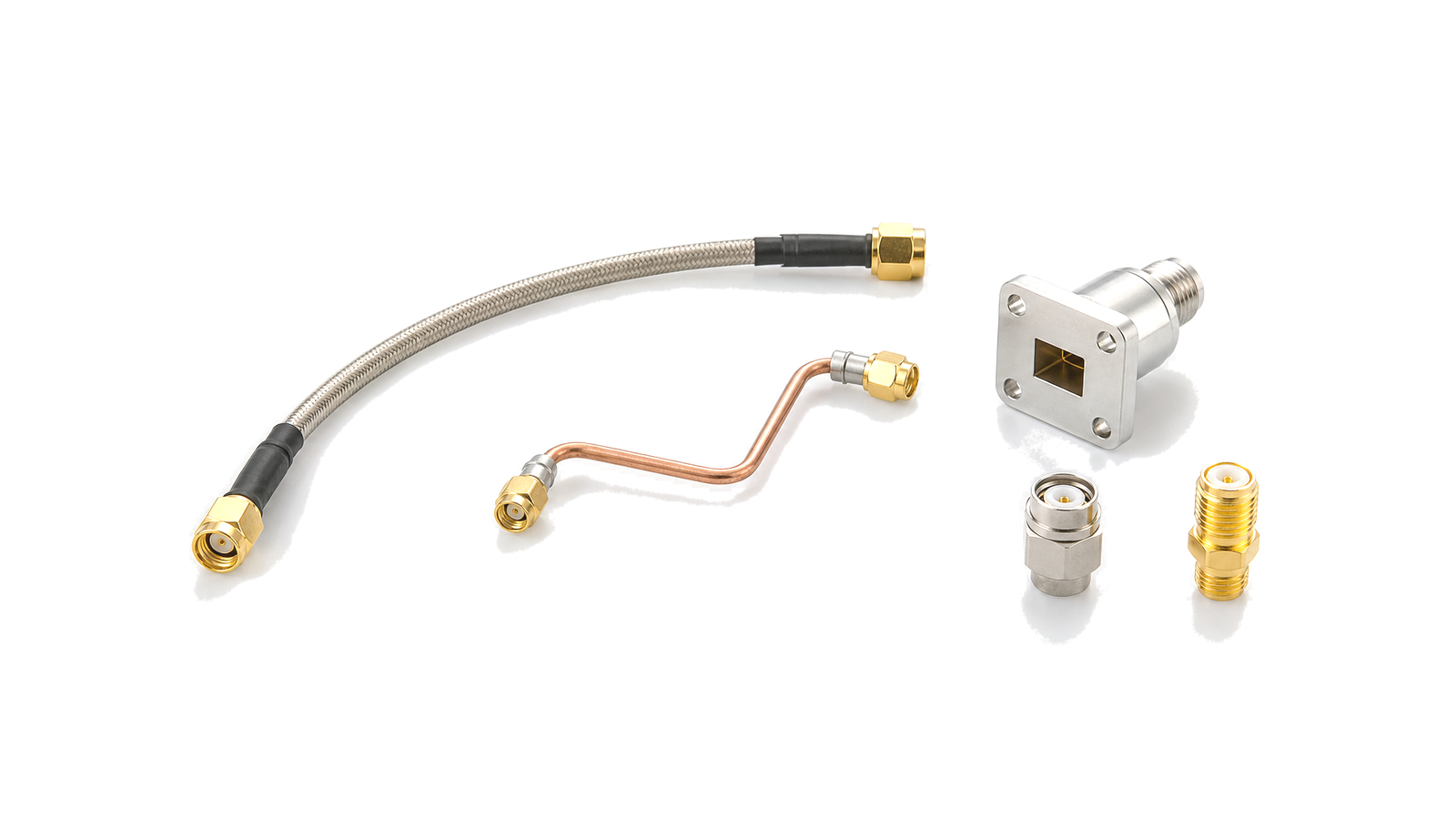
What RF hardware is required for test and measurement?
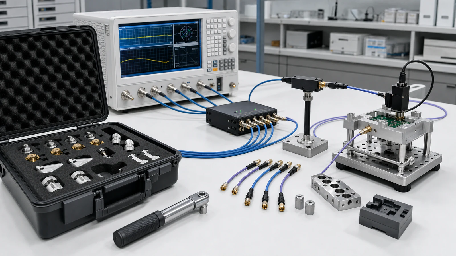
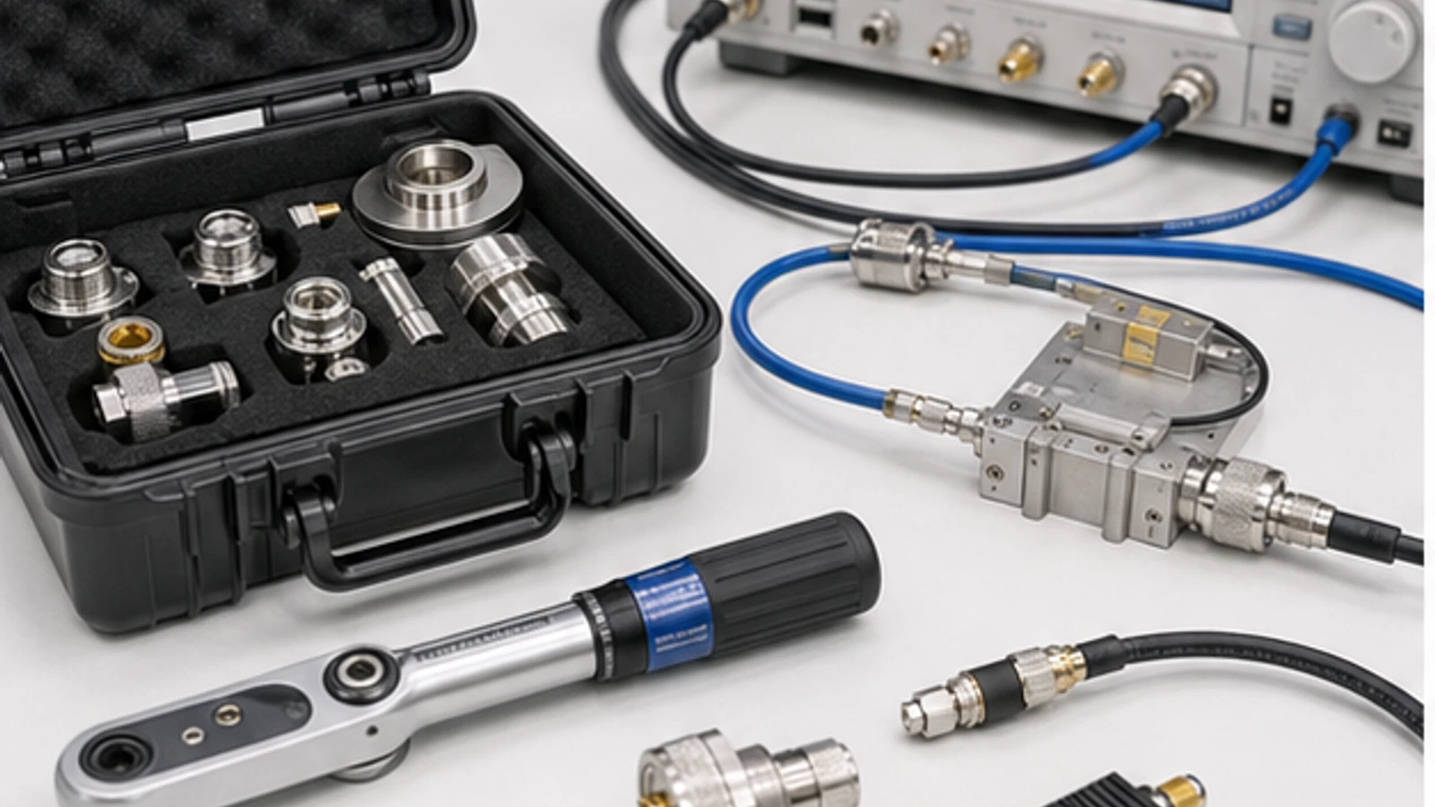
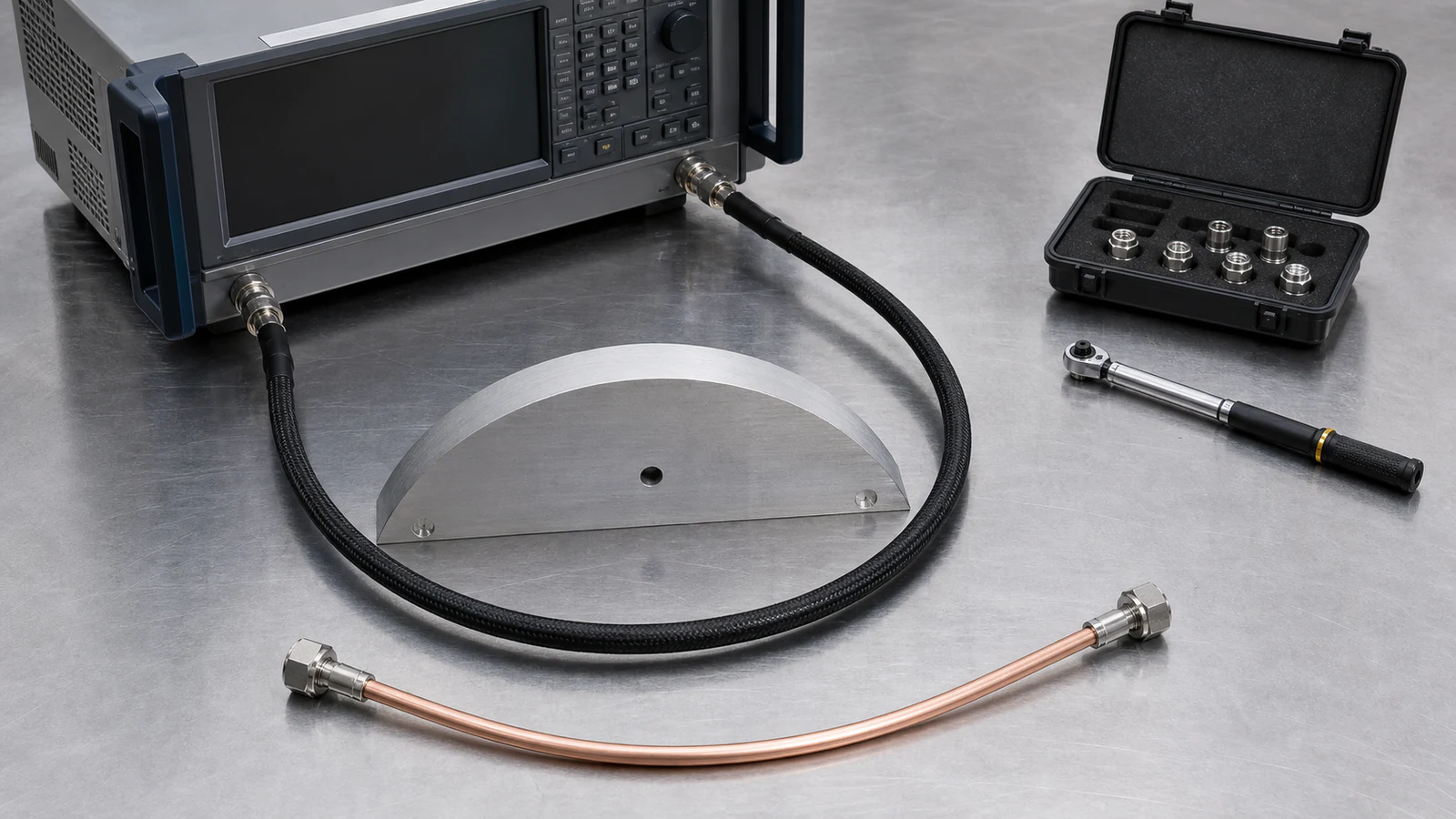
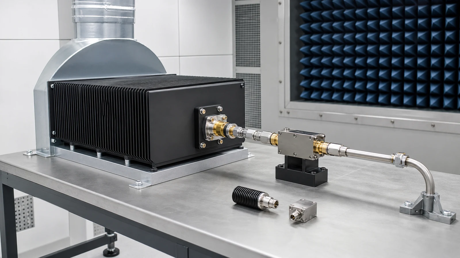
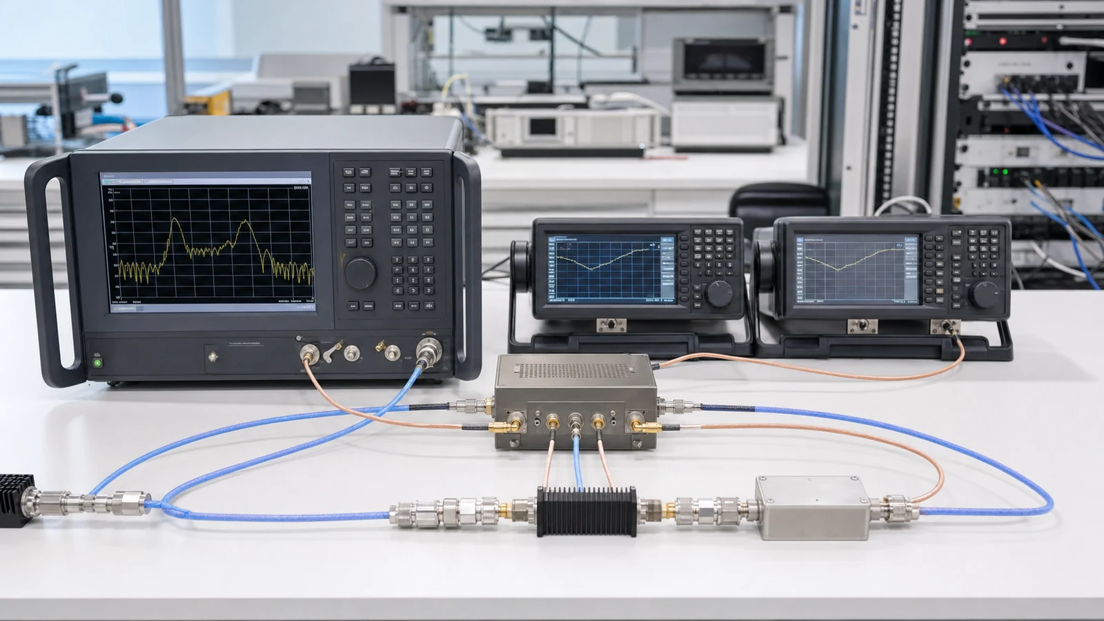
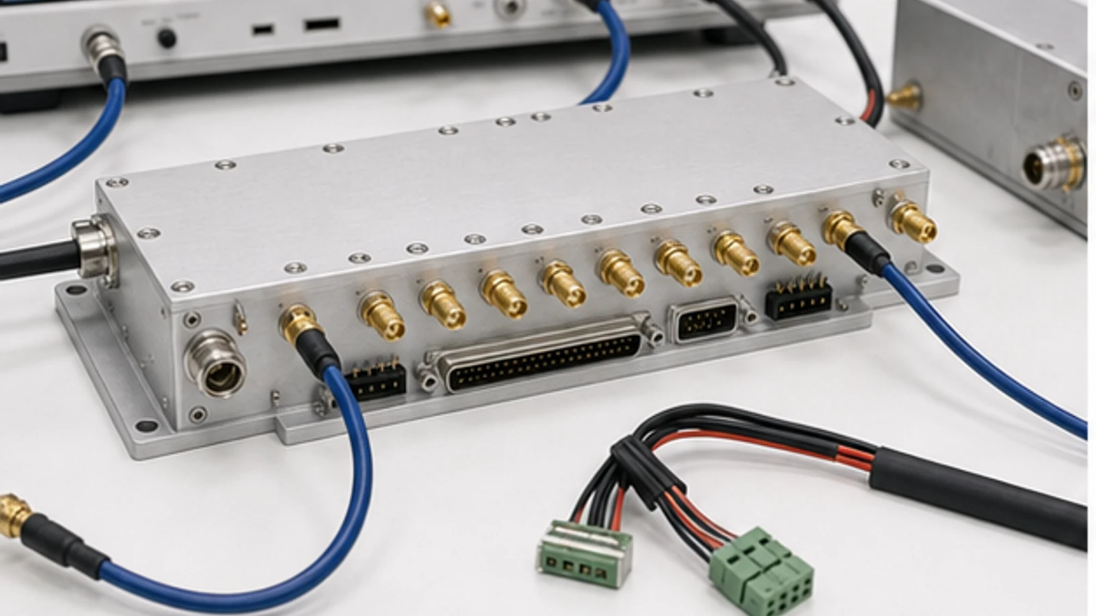
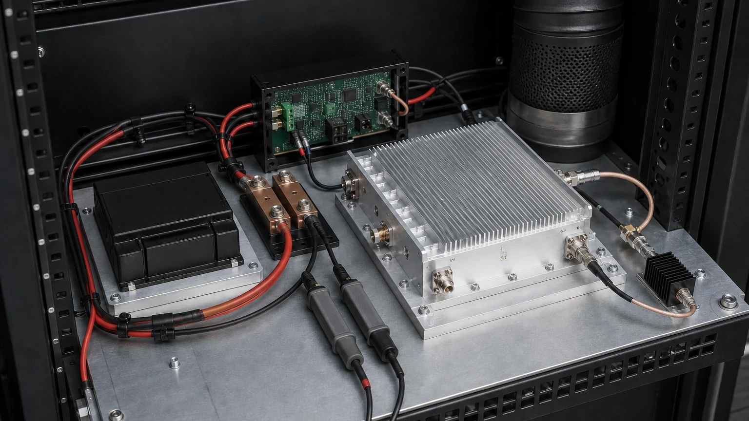
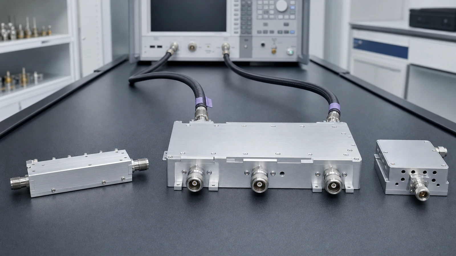
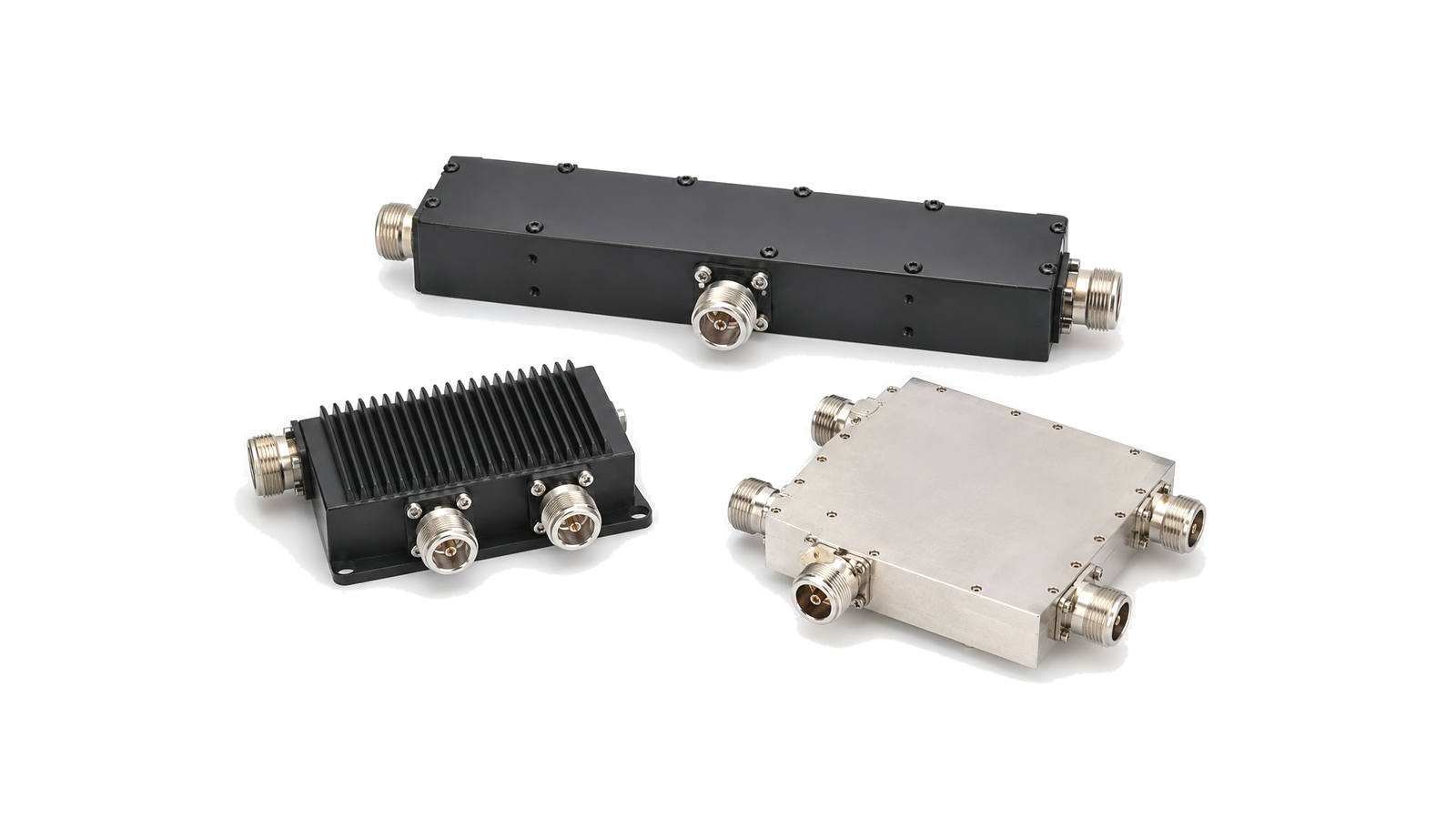
An RF test path uses controlled interconnect, adapters, switching, attenuation, power distribution, coupling, detection, loads, fixtures and reference or monitoring modules to connect an instrument to the device under test at defined reference planes. The required hardware depends on whether the station performs engineering characterization, incoming inspection, calibration, production acceptance, troubleshooting or field service. Measurement uncertainty and repeatability, not a visual bench layout, determine the architecture.
How is an RF test signal path designed?
Define the measurand, frequency and power range, required uncertainty and device interfaces first. Mark the calibration plane and every cable, adapter, switch, fixture, coupler and attenuator between that plane and the device. Build a path-loss and mismatch budget, then select hardware that can tolerate worst-case power without compromising sensitivity or repeatability. Automated stations also need state control, interlocks, settling time, health monitoring and a method to confirm the active path.
| Measurement task | RF path concern | Control evidence |
|---|---|---|
| Small-signal characterization | Reference-plane accuracy, fixture repeatability and dynamic range | Calibration method, residual error, cable stability and verification standards |
| Power or linearity testing | Power handling, loss, harmonics, thermal drift and safe shutdown | Path correction, sensor traceability, overload limits and interlock checks |
| Production acceptance | Cycle time, state repeatability and pass or fail consistency | Controlled procedure, golden or check standards, revision and result records |
| Monitoring or field service | Non-intrusive sampling, portability and environmental stability | Coupling calibration, connector care, self-test and field verification method |
Which RF specifications matter for test-hardware selection?
Frequency range and connector type are only the entry conditions. Insertion loss, return loss, isolation, directivity, attenuation accuracy, coupling factor, phase stability, repeatability and power rating determine measurement quality. Switching hardware adds settling and path-to-path repeatability. Fixtures add contact life, launch behavior and mechanical tolerance. Environmental range, torque, cable flexure and calibration interval must be considered when the setup moves or runs continuously.
Uncertainty should be assigned to the complete path. A component with a tight data-sheet tolerance can still produce a poor result if adapter mismatch, cable movement, connector wear or temperature drift is uncontrolled. Record which corrections are measured, which are assumed and which are included in the acceptance limit.
How do you test and verify RF test hardware?
Verify each path with known standards at the same reference planes used by the measurement procedure. Check loss, match, isolation and leakage across frequency, power and switch state. For power paths, confirm temperature rise and overload protection. For repeated connections, perform mating-cycle or contact-repeatability checks. Automated stations should run path verification at startup and at defined intervals, stop on invalid states and retain calibration, configuration and result identifiers with each record.
- Measurement task, frequency, power and dynamic range
- Device interfaces, connector cycles and fixture geometry
- Calibration and device reference planes
- Allowed loss, mismatch, leakage and uncertainty
- Switch states, settling, control and interlocks
- Environmental and mechanical repeatability limits
- Calibration interval, check standards and traceability
- Acceptance procedure, data format and revision control
Architecture and approval boundary
RF hardware must be assessed as part of the complete measurement setup; uncertainty cannot be assigned without the full configuration and procedure. Final approval requires reference-plane, calibration, power, repeatability and acceptance evidence for the actual station.