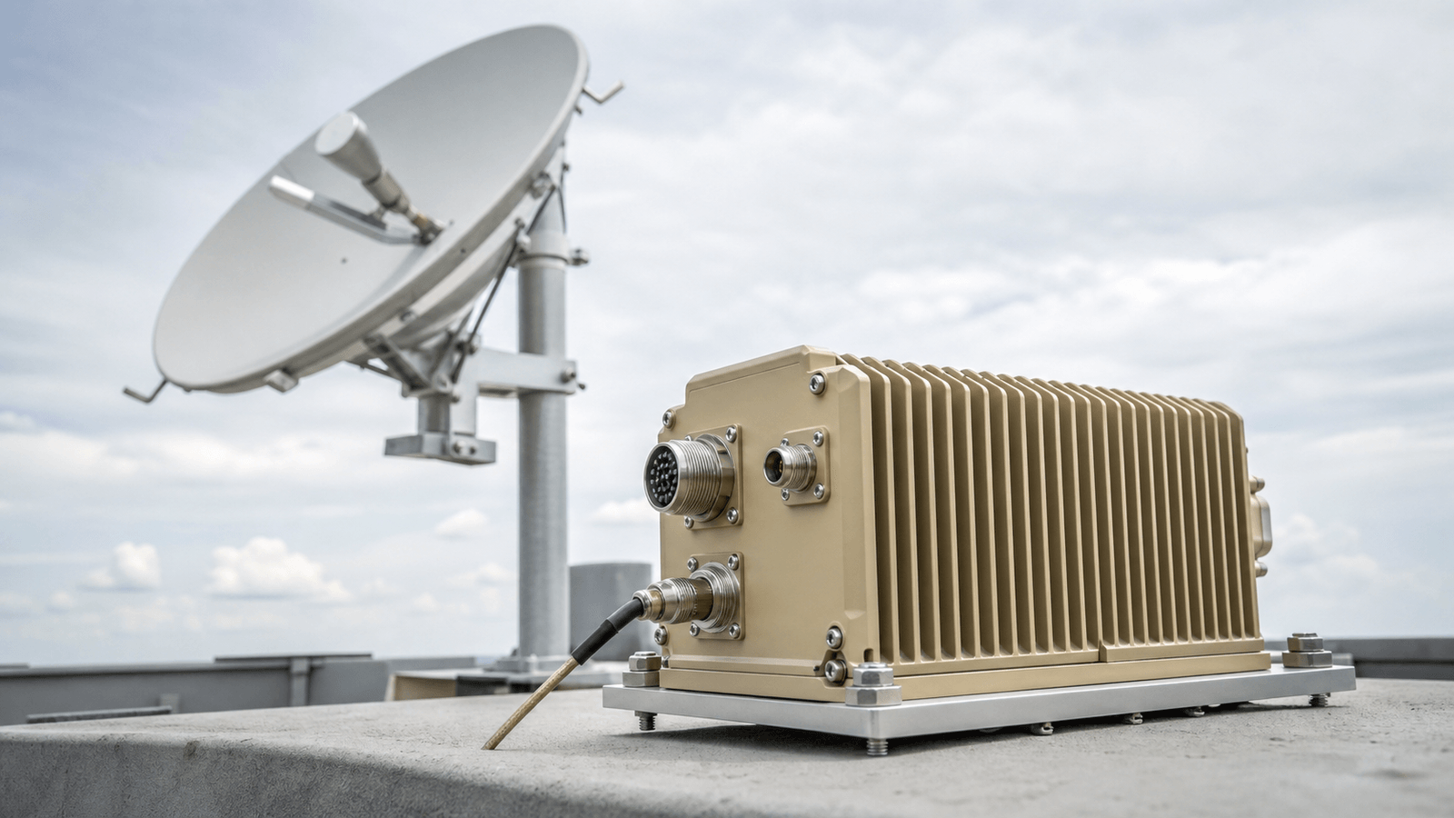
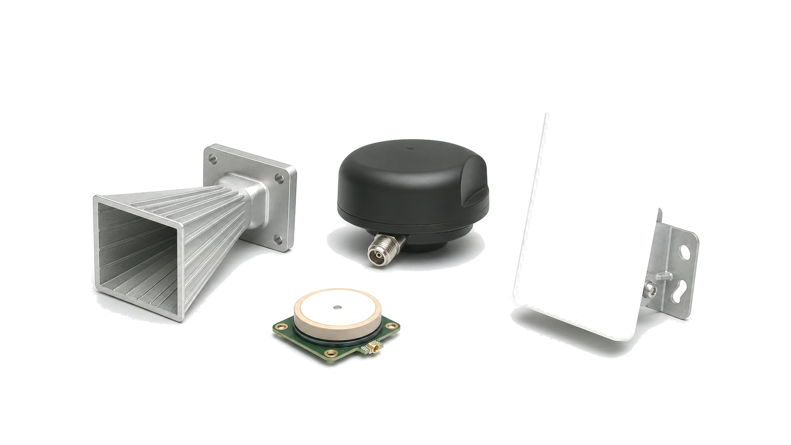
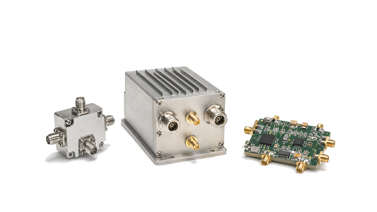
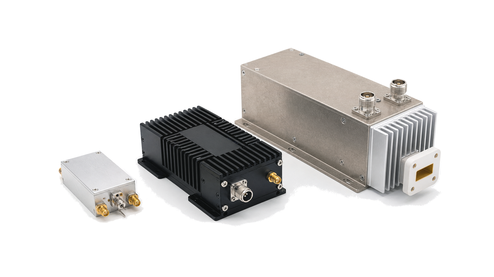
What must a communications or SATCOM RF system definition close?
It must close the end-to-end link budget and convert that budget into named transmit, receive, conversion, filtering, interconnect, control and verification requirements at agreed reference planes. A useful definition starts with service availability, data rate, waveform, band, coverage geometry and environmental assumptions. It then distinguishes uplink from downlink and separates propagation margin from hardware margin, so EIRP, G/T, sensitivity and linear output retain their distinct engineering meanings.
Engineering decisions covered by the solution
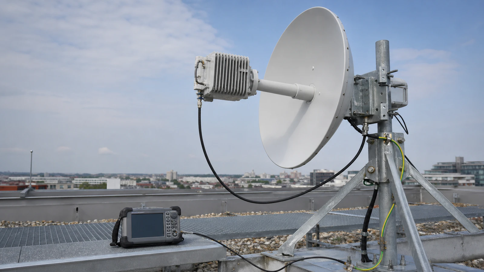
- Communications and SATCOM RF Systems architecture: maps the ground or terrestrial segment from modem and IF through conversion, gain, filtering, feed and antenna interface
- Communications and SATCOM RF Systems design requirements: turns data rate, availability, propagation and interference assumptions into measurable RF allocations
- Communications and SATCOM RF Systems integration: aligns RF, DC, control, timing, mechanical and redundancy interfaces before equipment is committed
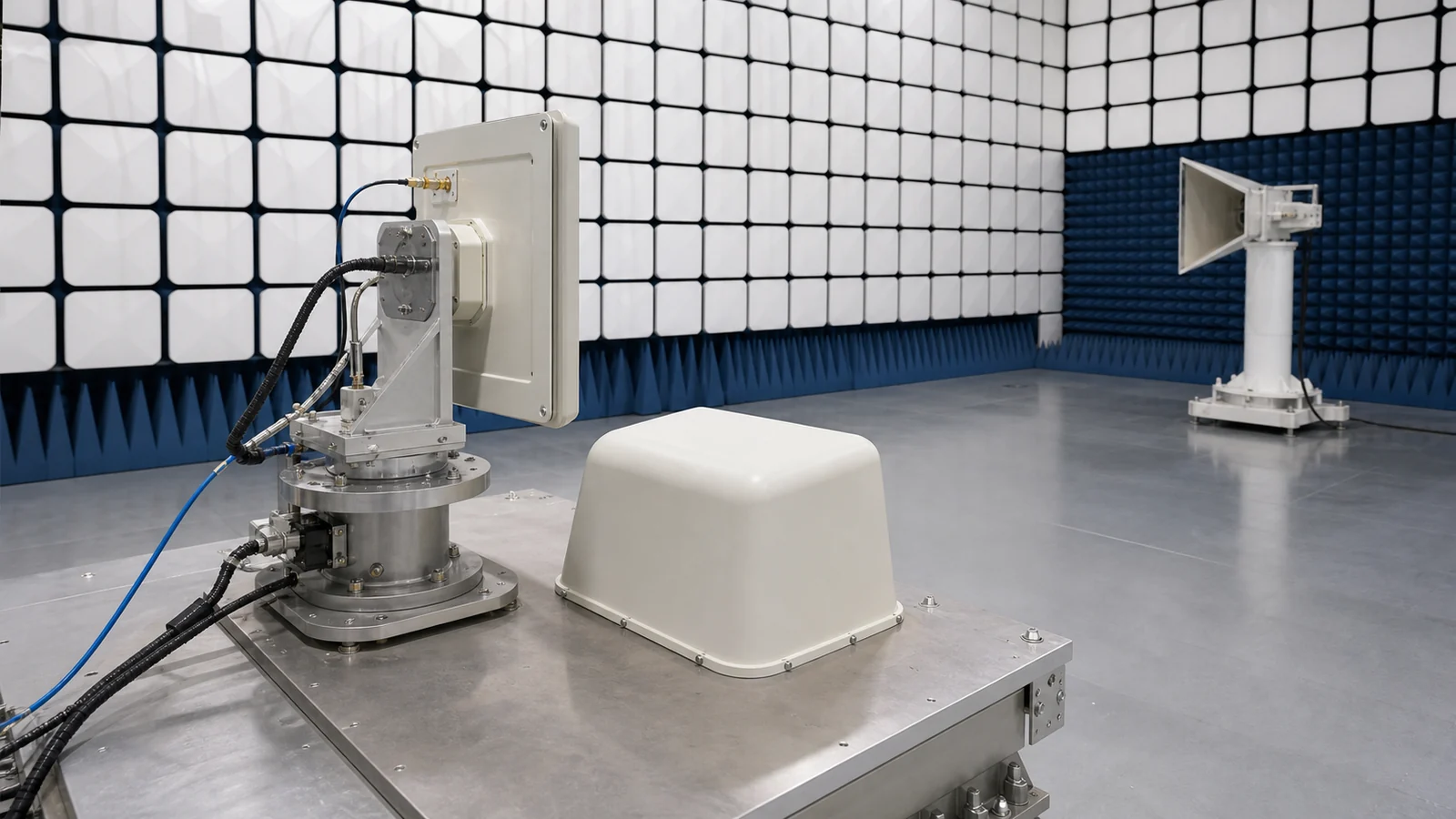
- Communications and SATCOM RF Systems test and verification: proves acquisition, demodulation, spectral compliance and failover at the contractual reference planes
Start with the service, geometry and reference planes
State whether the path supports cellular infrastructure, point-to-point microwave, gateway traffic, telemetry tracking and command, payload data or another service. Record uplink and downlink bands, polarization, duplex method, channel bandwidth, modulation and coding, required availability, latency and site geometry. Name the modem, IF, converter, HPA, LNA/LNB, feed and antenna planes. A dB value without its direction and plane cannot be allocated or accepted.
Close the link budget in every credible operating state
For transmit, include conducted power, output back-off, feeder or waveguide loss, antenna gain, pointing and polarization loss to obtain EIRP. For receive, include antenna gain, system noise temperature, front-end loss and receiver noise contribution to obtain G/T and available carrier-to-noise density. Add free-space loss, atmospheric and rain attenuation, implementation loss, interference allowance and the required Eb/N0 or C/N. Keep clear-sky, degraded weather, edge-of-coverage, acquisition and redundancy states separate instead of hiding them in one margin.
Design receive sensitivity without sacrificing blocker tolerance
Loss ahead of the first low-noise stage directly raises system noise temperature, so feed, waveguide, filter and switching losses must be budgeted before selecting LNA gain. At the same time, adjacent carriers, uplink leakage, local transmit coupling and strong terrestrial emitters can compress the front end. Specify noise figure or noise temperature, gain distribution, input P1dB, out-of-band rejection, image response, AGC range, spurious response and recovery behavior at the actual antenna-side levels.
Define linear transmit power for the real waveform
The required RF output is not the saturated rating. Translate the waveform PAPR, EVM, spectral mask, adjacent-channel limit and intermodulation target into output back-off at the worst temperature and duty cycle. Include converter and driver headroom, harmonic filtering, reflected-power monitoring, mismatch survival, mute timing and safe shutdown. For multi-carrier service, assess composite power and intermodulation with the planned carrier loading rather than a single-tone assumption.
Integrate frequency, control, redundancy and outdoor interfaces
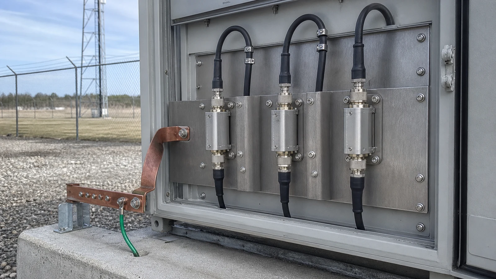
Document RF, LO and IF ranges, injection side, image bands, reference clocks, phase-noise allocation and frequency accuracy. Freeze connector or flange, impedance, supply rails, control protocol, alarms, telemetry, switching sequence and failover time. Redundant chains need defined isolation and state transfer, not only duplicated hardware. Outdoor assemblies also require temperature derating, sealing, corrosion control, grounding, surge strategy, maintainable cable routing and a known thermal path.
Verify the link from calibrated components to end-to-end operation
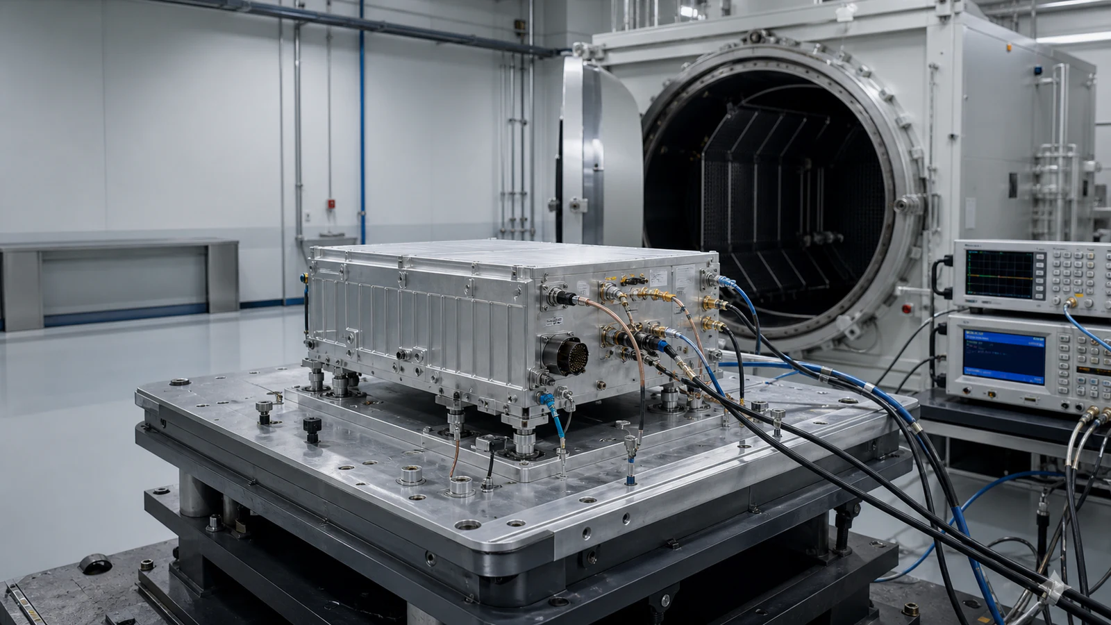
Characterize gain, noise, S-parameters, compression, linearity, phase noise and filter response at component and assembly planes. De-embed test cables and adapters. Then connect the modem or waveform source and reproduce delay, Doppler, attenuation, fading, interference and switching events under controlled conditions. Acceptance evidence should include acquisition threshold, sensitivity or BER, EVM, spectral emissions, output power, link recovery, redundancy transfer, temperature corners, calibration state and measurement uncertainty.
Minimum allocation record for a communications RF path
| Decision area | Required project input | Acceptance evidence |
|---|---|---|
| Service and link | Uplink/downlink, data rate, waveform, availability, geometry and weather model | Signed link budget with normal and degraded-state margins |
| Receive path | G/T or sensitivity, noise temperature, blockers, gain and AGC range | Calibrated noise, gain, rejection, compression and demodulation results |
| Transmit path | EIRP, waveform loading, back-off, mask, duty cycle and mismatch | Power, EVM, spectrum, intermodulation and protection records |
| Interfaces | RF/IF/LO planes, flange or connector, power, control, timing and alarms | Interface drawing, sequence log and monitored-state evidence |
| Operations | Temperature, ingress, redundancy, maintenance and calibration interval | Environmental, failover, recovery and uncertainty-controlled reports |
Inputs to include in a communications or SATCOM RFQ
- Service type, deployment geometry, uplink and downlink bands and regulatory region
- Data rate, channel width, modulation, coding, PAPR and spectral limits
- Named antenna, feed, RF, IF, modem and measurement reference planes
- Required EIRP, G/T, sensitivity, Eb/N0 or C/N and link availability
- Rain, atmospheric, pointing, polarization, feeder and implementation losses
- Adjacent carriers, blockers, self-interference, duplex isolation and protected bands
- Connectors or flanges, impedance, clocks, power, control, telemetry and alarms
- Duty cycle, ambient range, cooling, sealing, grounding and maintenance access
- Redundancy mode, switching time, safe state and recovery behavior
- Calibration, uncertainty, acceptance limits, test configuration and deliverable data
Solution boundary
The scope covers terrestrial communications and satellite ground-segment RF architecture from a defined modem, IF or RF plane to the antenna-feed interface. Spacecraft payload design, network protocol engineering, propagation-site surveys, spectrum licensing, civil works and antenna structural design remain separate disciplines, although their approved assumptions must enter the RF budgets.