LCRF

Privacy preferences

Choose optional purposes independently. You can change or withdraw your choice at any time from the footer.

Strictly necessary

Required for security, session functions and storing your privacy choice.

Always active
Preferences

Remembers optional display or language settings when these features are enabled.

Analytics

Uses first-party visitor and session identifiers to measure pages, referrals and inquiry interactions.

Marketing

Allows marketing measurement or third-party advertising technologies if they are introduced in the future.

PA Characterization Bench

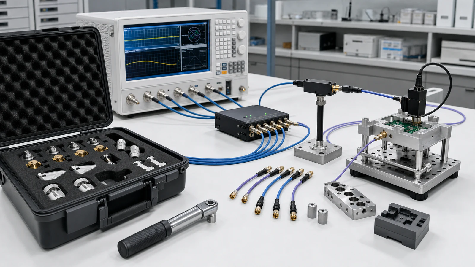
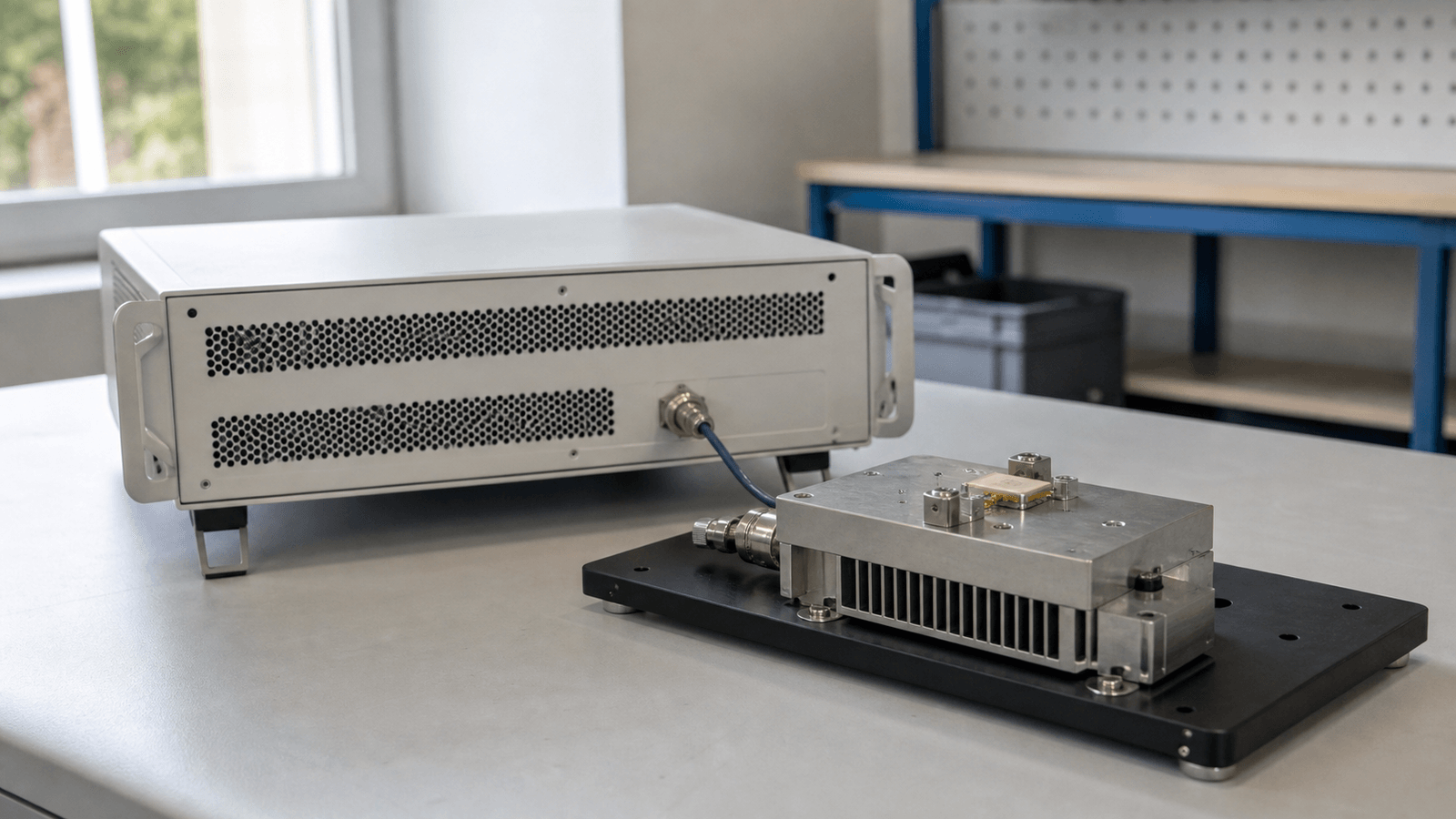
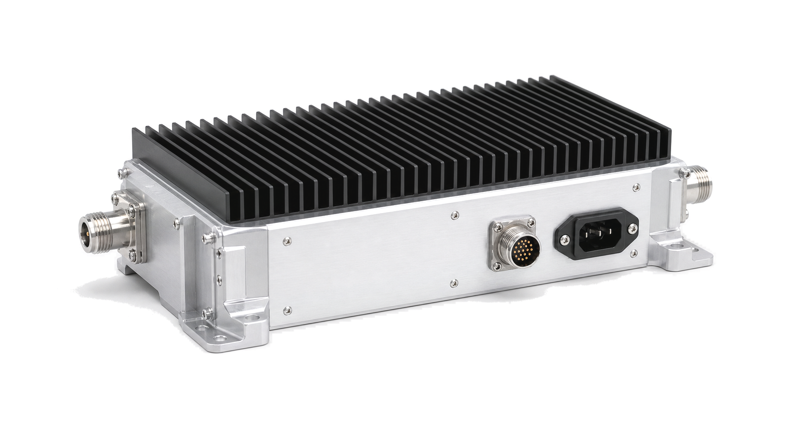
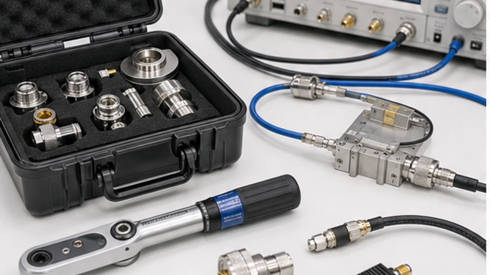
PA characterization benches measure RF power amplifier behavior under controlled frequency, drive, load, supply and thermal conditions. Typical benches combine sources, meters, couplers, loads, fixtures, bias supplies, protection monitoring and calibration.

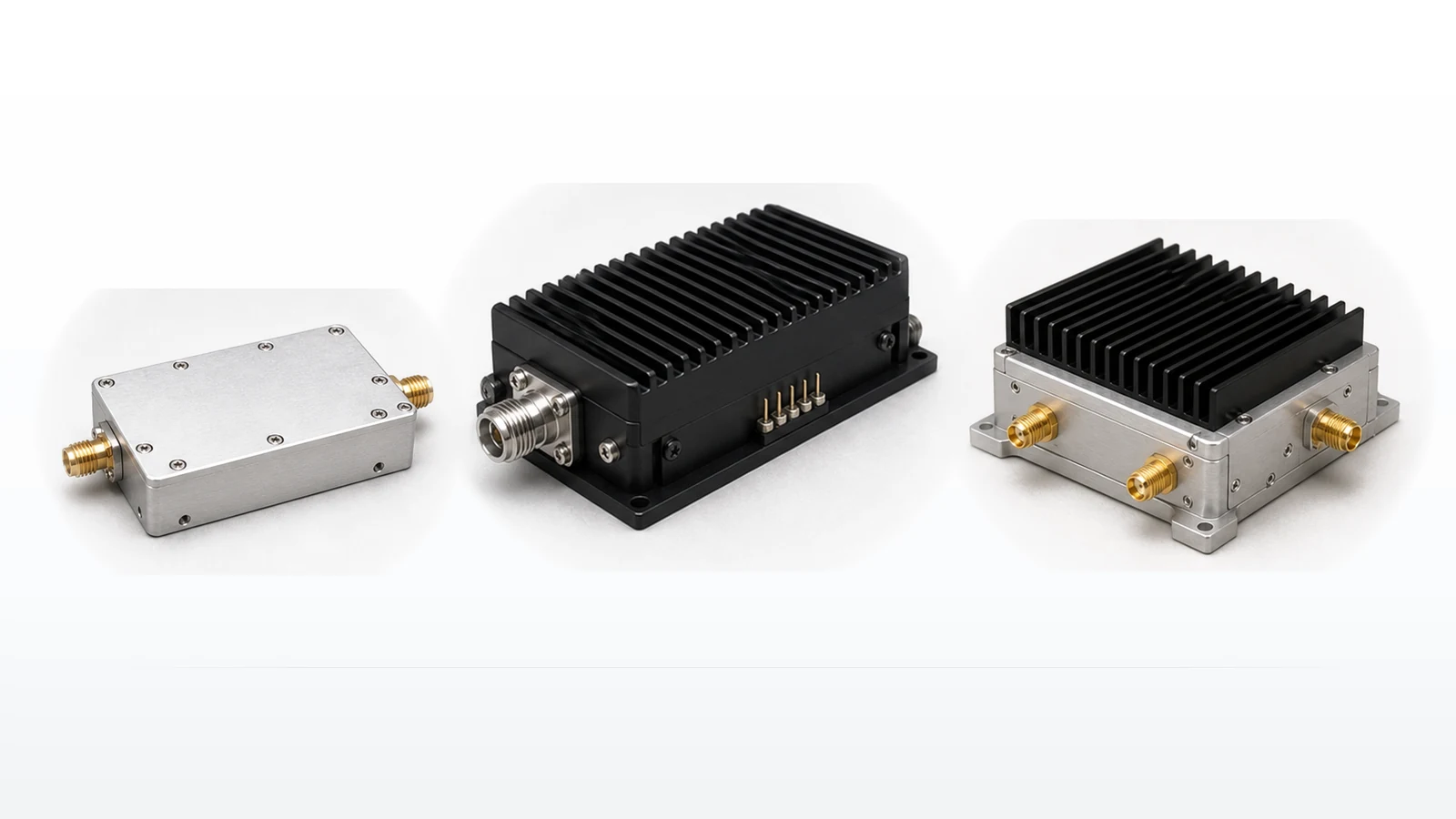
PA Characterization Bench RF solution visual

PA Characterization Bench

A PA characterization bench is used to measure how an RF power amplifier behaves under defined electrical, load and thermal conditions. The bench places the amplifier under test between controlled RF drive, calibrated measurement paths, suitable loads and bias or supply hardware.

Measurement path

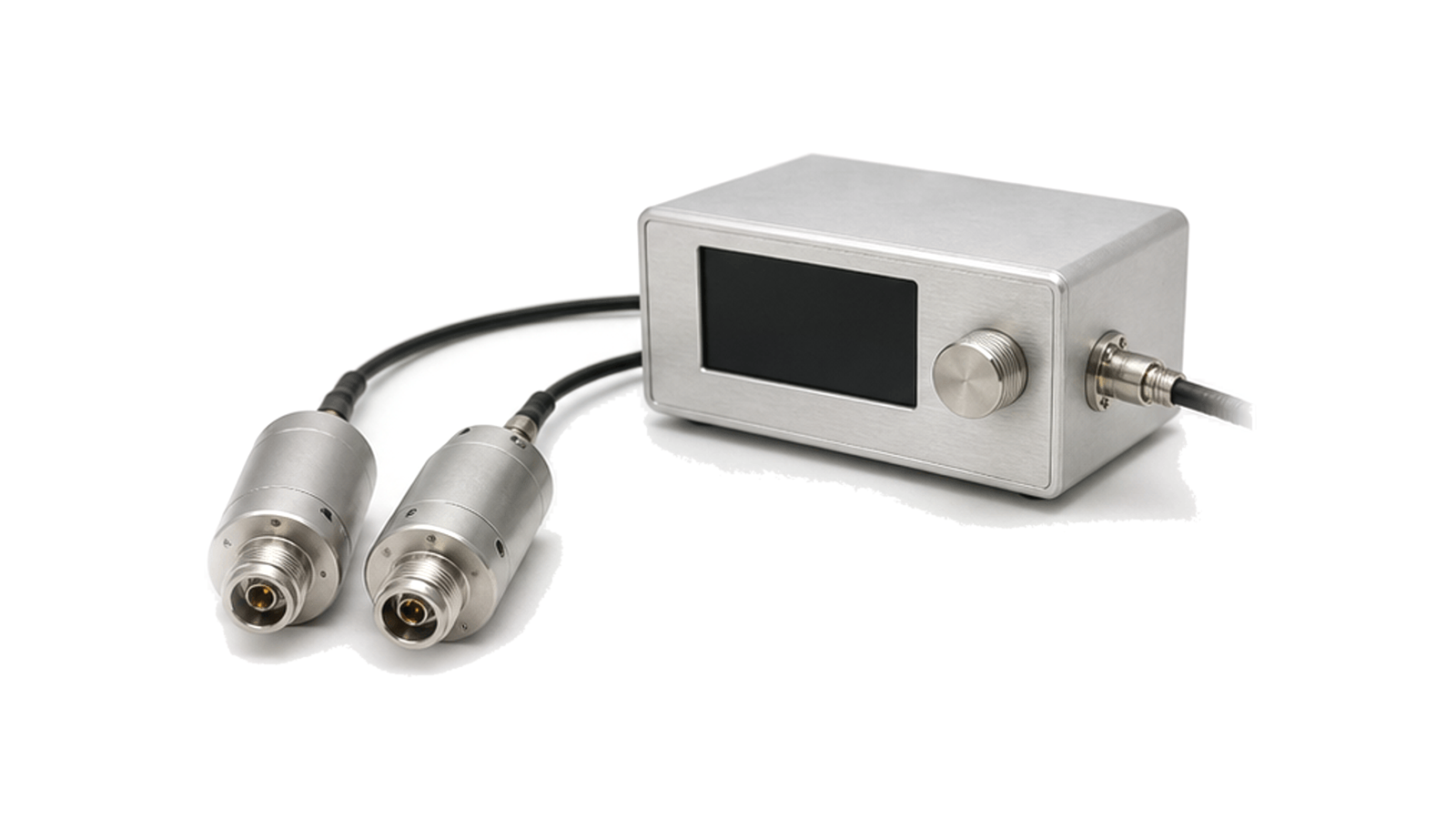
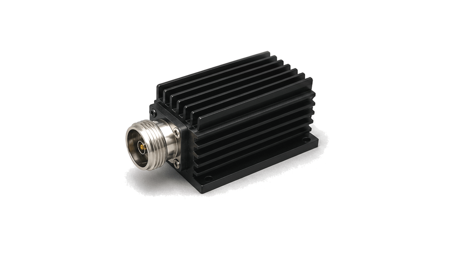
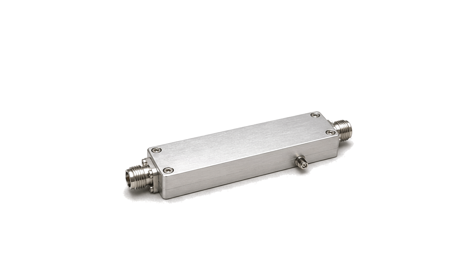
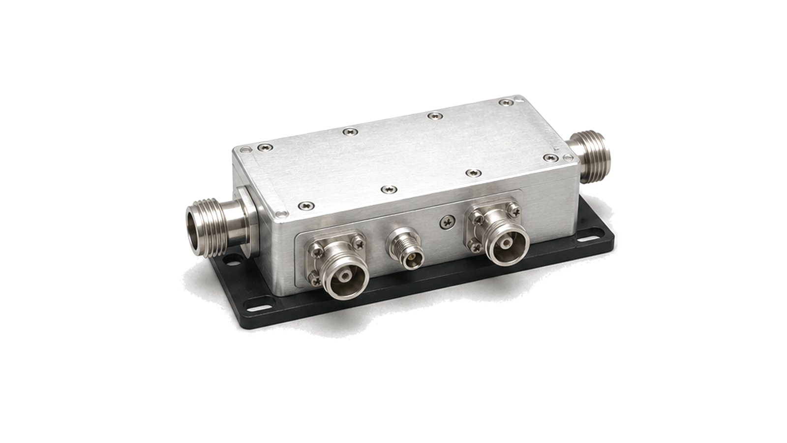
Typical setups include RF sources, power meters or sensors, directional couplers, attenuators, loads, fixtures, VSWR or reflected-power monitoring, bias supplies, thermal hardware and data capture. The arrangement should keep the drive path, output path and monitoring path clear so results can be compared across models, revisions and operating points.

Data to confirm

Useful data includes test frequency, drive level, output power, gain, compression behavior, harmonic limits, load condition, supply current, heat-sink state, calibration reference and protection response.
Articles

FAQ

How should RF P1dB and two-tone intermodulation tests differ?

P1dB is a single-tone gain-compression sweep, while two-tone IMD measures nonlinear mixing products with stated tone spacing, per-tone power and system residual checks; the results answer different questions.

What thermal-interface data are needed before selecting air or liquid cooling for an RF power module?

Define dissipated heat, temperature reference, interface stack, airflow or coolant conditions and loss-of-cooling behavior before comparing cooler ratings.

How often should an RF test path be verified with a check standard or recalibrated?

Use both time-based intervals and event triggers, with an independent check standard that can reveal drift, cable or connector damage, switch-state change and fixture instability between full calibrations.

What is an RF measurement reference plane, and when is fixture de-embedding required?

The measurement reference plane is the electrical boundary where a corrected value is claimed; de-embedding is needed only when a characterized fixture network must be removed to report at a different DUT plane.

Engineering inquiry

Share your RF requirement

Share the product, operating requirements and project context. Our engineering team will route your request to the right specialist.

AttachmentsAttach drawings, BOMs, specifications or test files. Up to 5 files, 10 MB each and 25 MB total.
or drag and dropPDF, DOCX, XLSX, CSV, TXT, JPG, PNG, S1P and S2P
Typically reviewed within one business dayProject information is handled confidentially