What RF hardware is required for communications and connectivity?
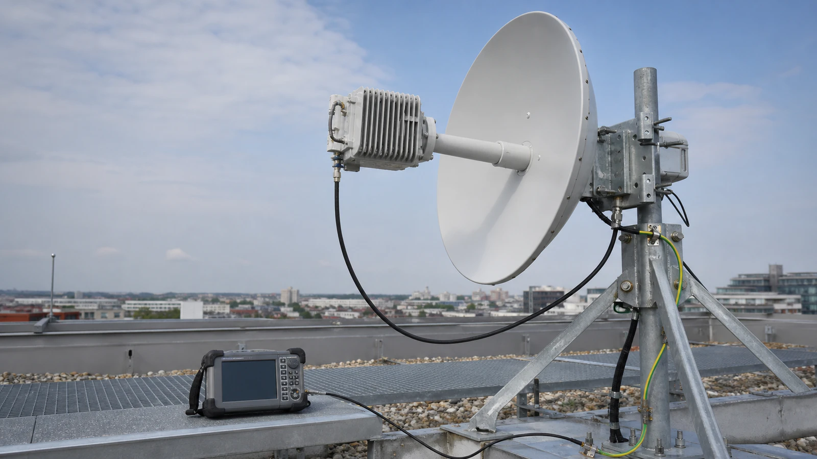
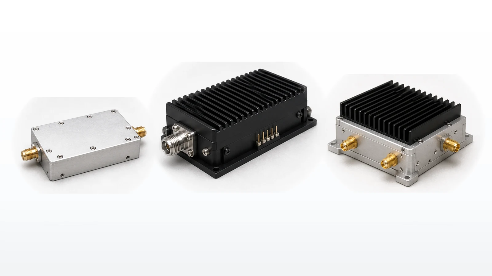
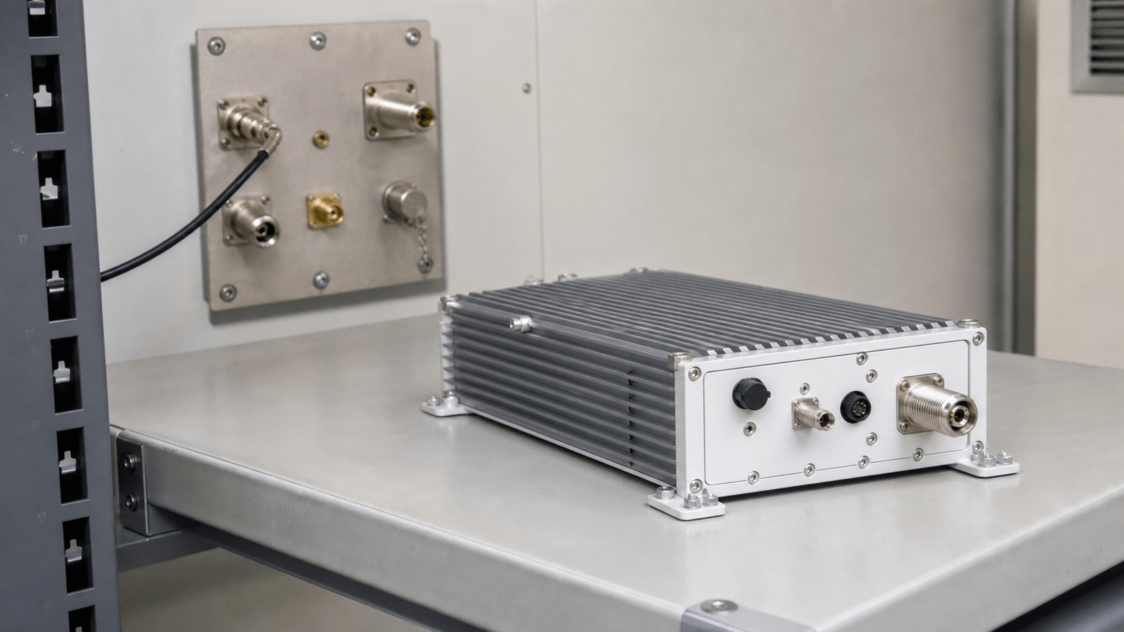
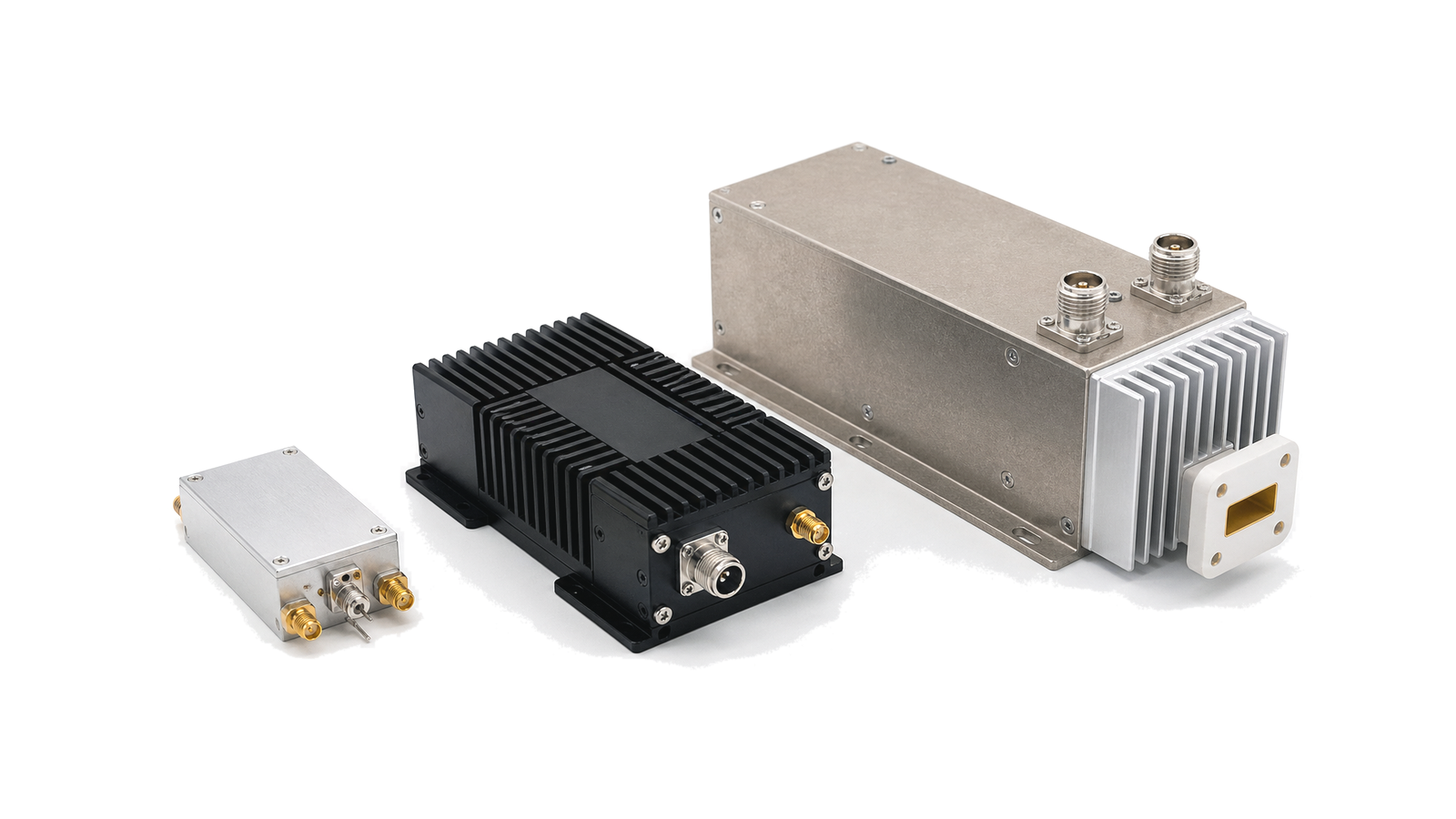
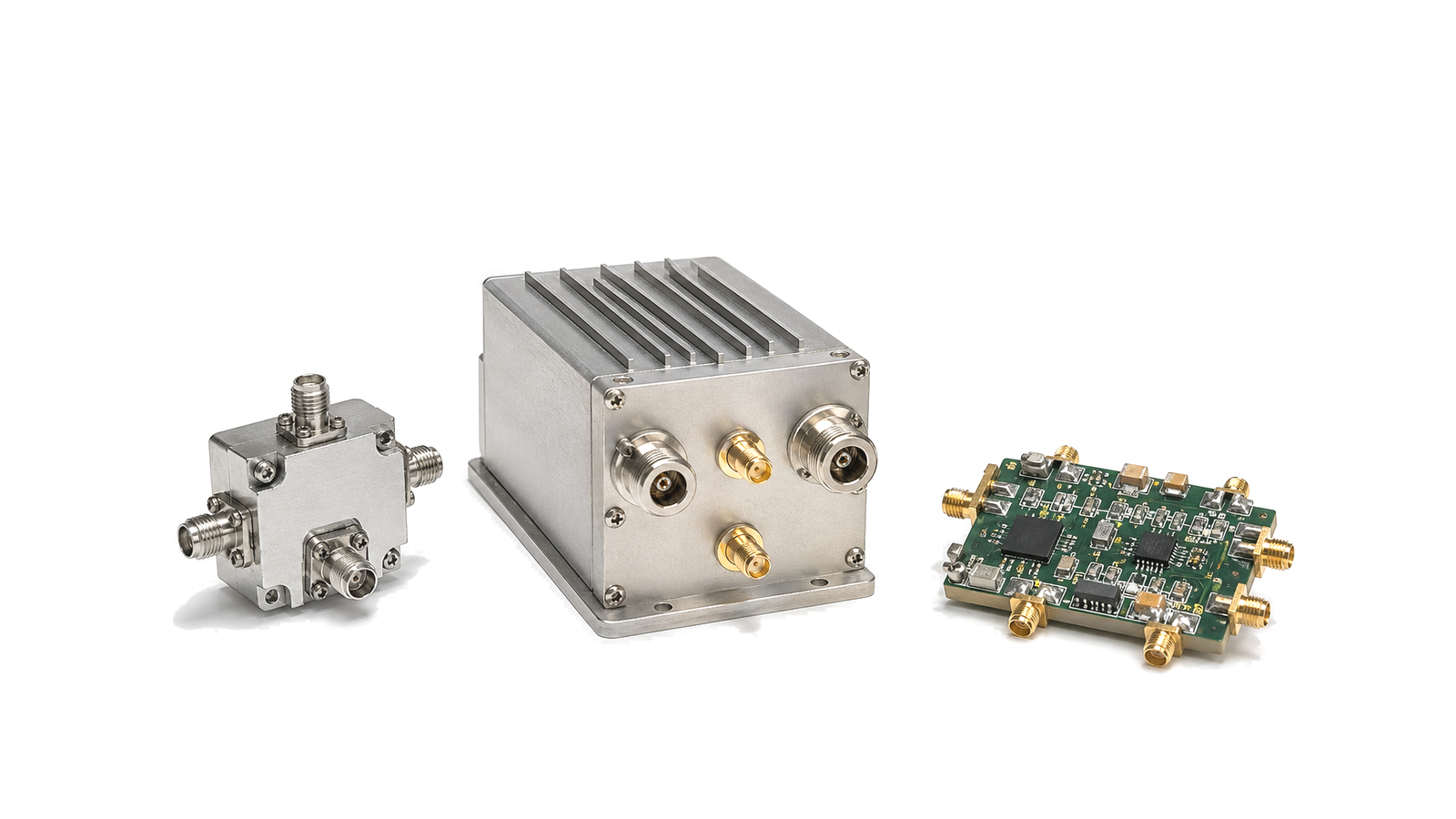
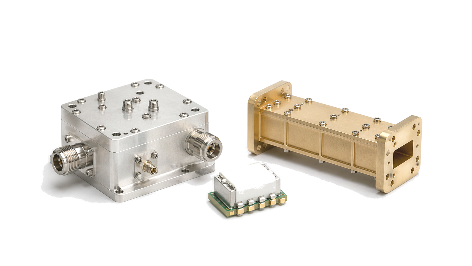
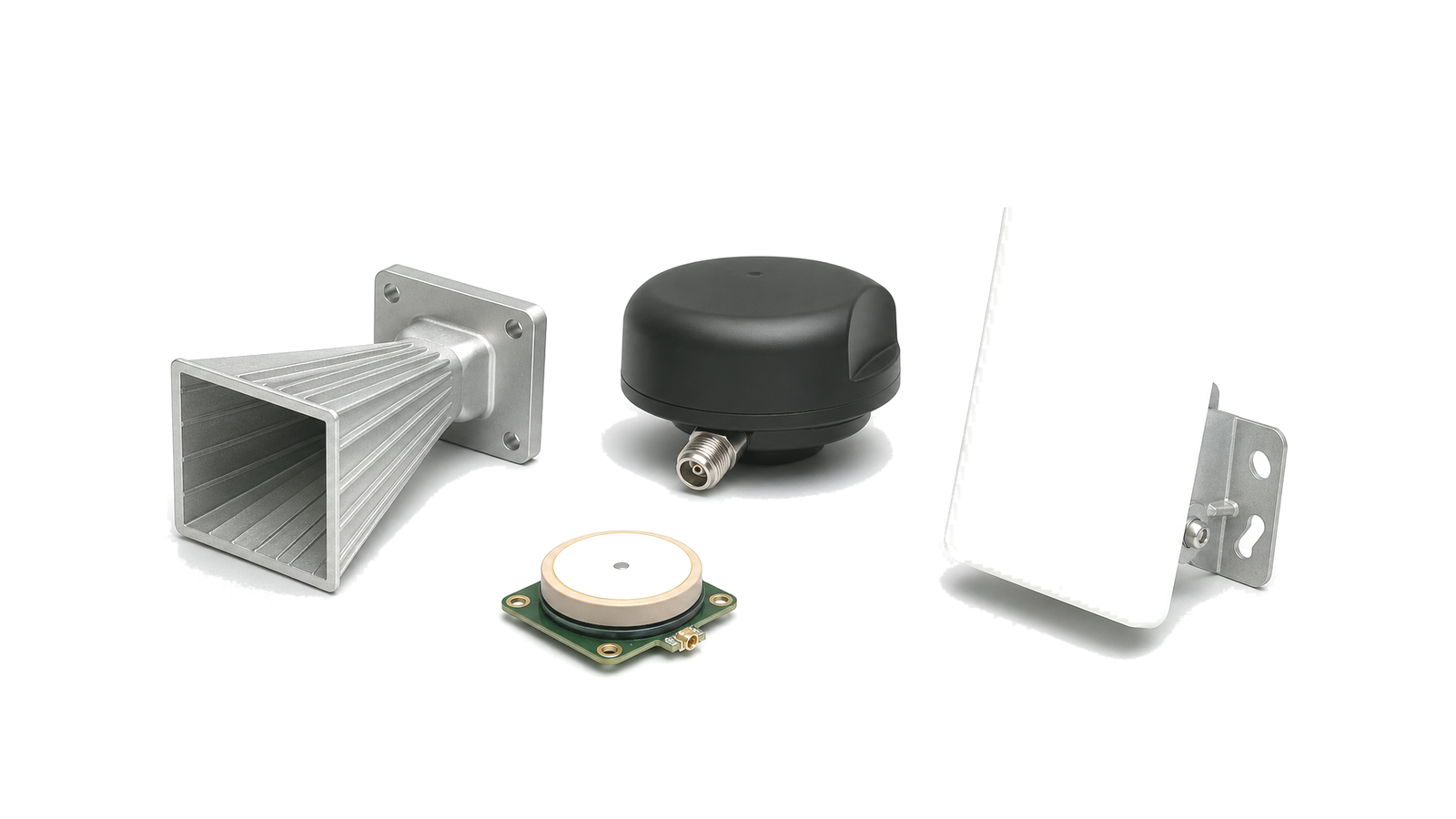
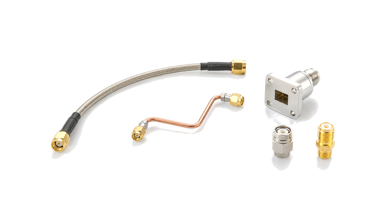
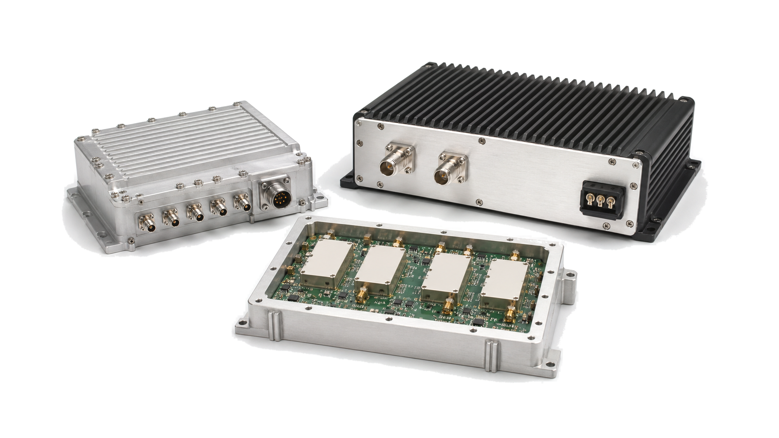
A communication link normally requires frequency generation or timing, transmit and receive gain, frequency conversion where bands differ, channel filtering, switching or duplexing, protected interconnect and an antenna interface. The exact hardware depends on whether the system is a base station, private wireless link, microwave backhaul path, satellite terminal, tactical radio or another fixed or mobile connection. The mission and link budget define the architecture; a generic component list does not.
How is an RF signal chain designed for communications and connectivity?
Begin with the service area, path distance, data rate, channel bandwidth, duplex method and allowed spectrum. Build separate transmit and receive budgets at named reference planes, including antenna gain, cable and filter loss, fading or installation margin, transmitter back-off and receiver noise. Then place gain, filtering, conversion and switching stages so that wanted signals remain above the sensitivity target while blockers and transmit leakage stay below compression or desensitization limits.
| Architecture decision | Required inputs | Result to document |
|---|---|---|
| Channel and frequency plan | Operating bands, channel widths, duplex spacing and prohibited emissions | RF, LO and IF bands plus filter and switching states |
| Transmit path | Average power, PAPR, modulation quality, antenna and feed loss | Required gain, output back-off, filtering and thermal boundary |
| Receive path | Sensitivity, noise budget, blockers, coexistence and antenna isolation | LNA gain, filtering, dynamic range and protection limits |
| Timing and control | Reference accuracy, phase noise, synchronization and switching sequence | Reference distribution, lock behavior and control interfaces |
Which RF specifications matter for communication hardware selection?
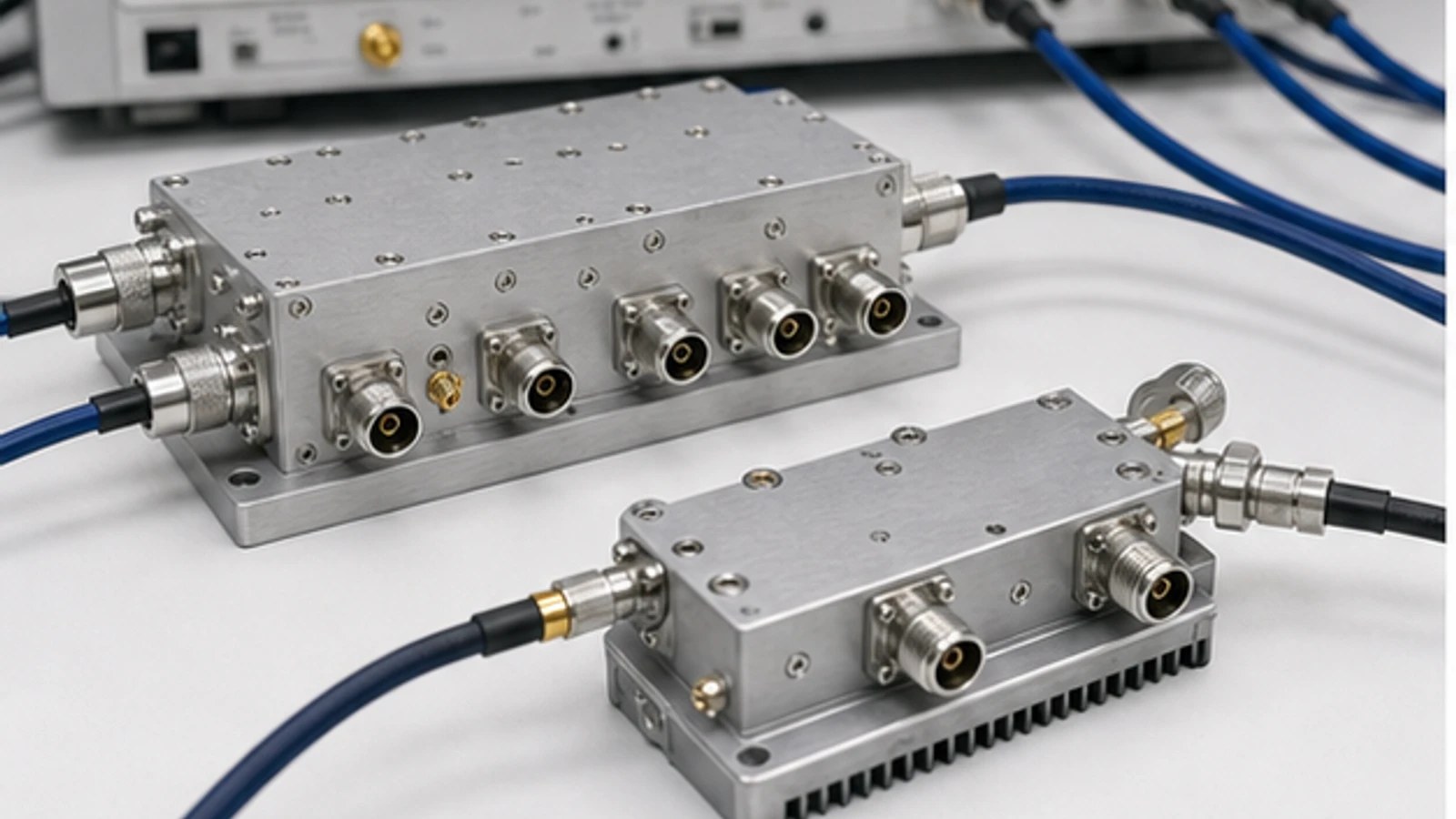
Frequency coverage, gain, output level and noise must be tied to the intended channel and reference plane. Modulated transmitters require EVM, ACPR or spectral-mask performance at the required average power and back-off. Receivers require noise figure, linearity, blocker tolerance and image or spurious rejection. Filters, switches and interconnect add loss, isolation and power constraints. Timing accuracy, phase noise, latency, supply, environmental exposure and antenna interface complete the system boundary.
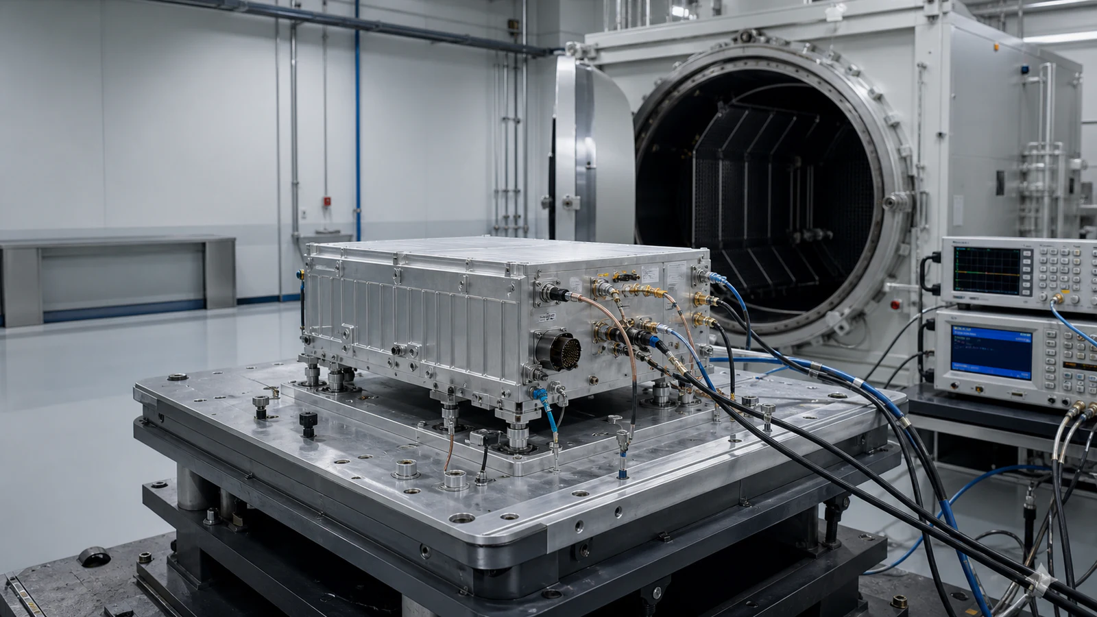
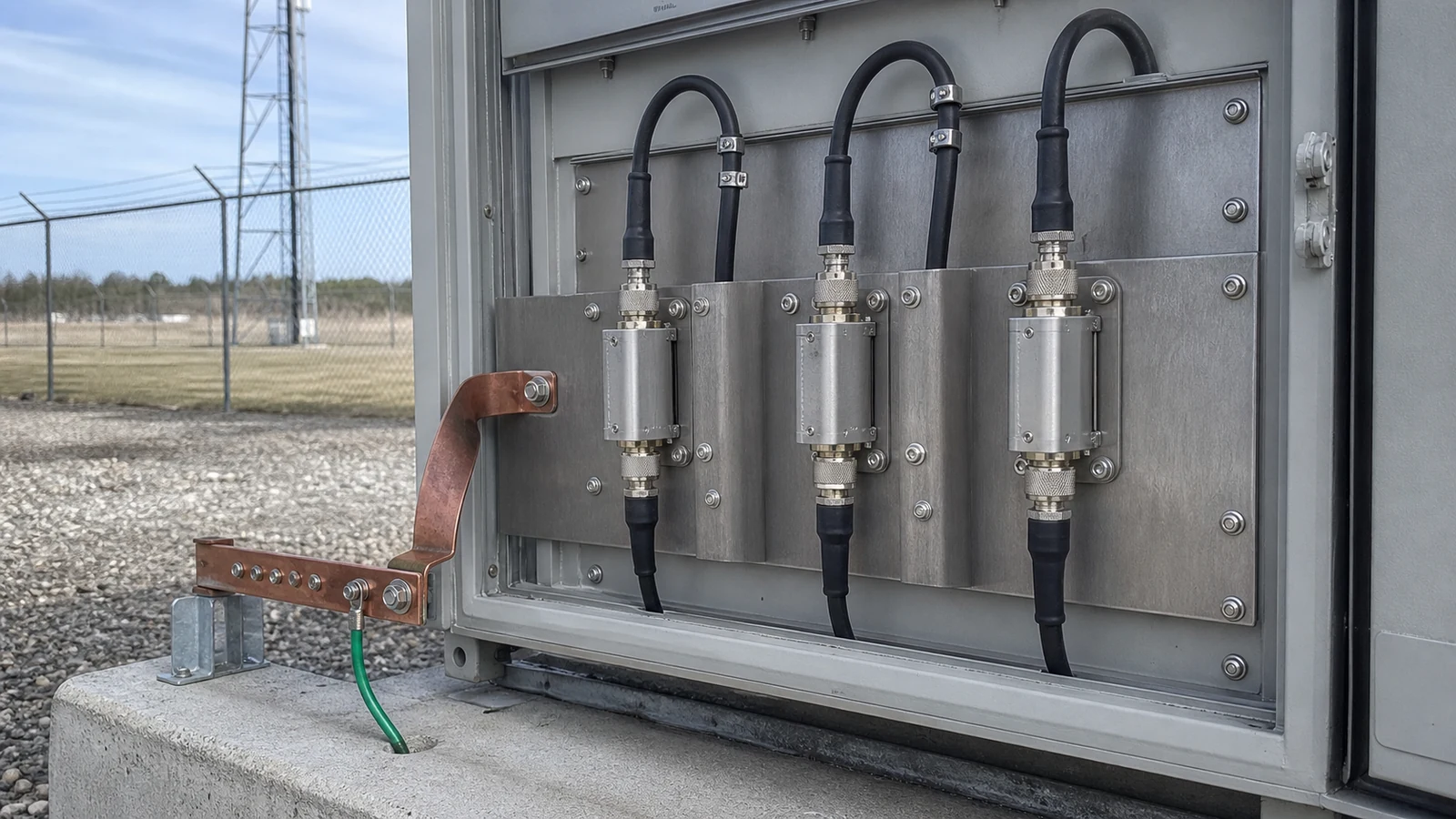
Compare hardware under one condition set. A typical gain value cannot replace a minimum over temperature, and saturated output cannot replace linear modulated power. For outdoor, mobile or remote installations, include enclosure, ingress, vibration, altitude, cooling, cable routing, service access and surge or ESD exposure during selection.
How do you test and verify RF hardware for communications and connectivity?
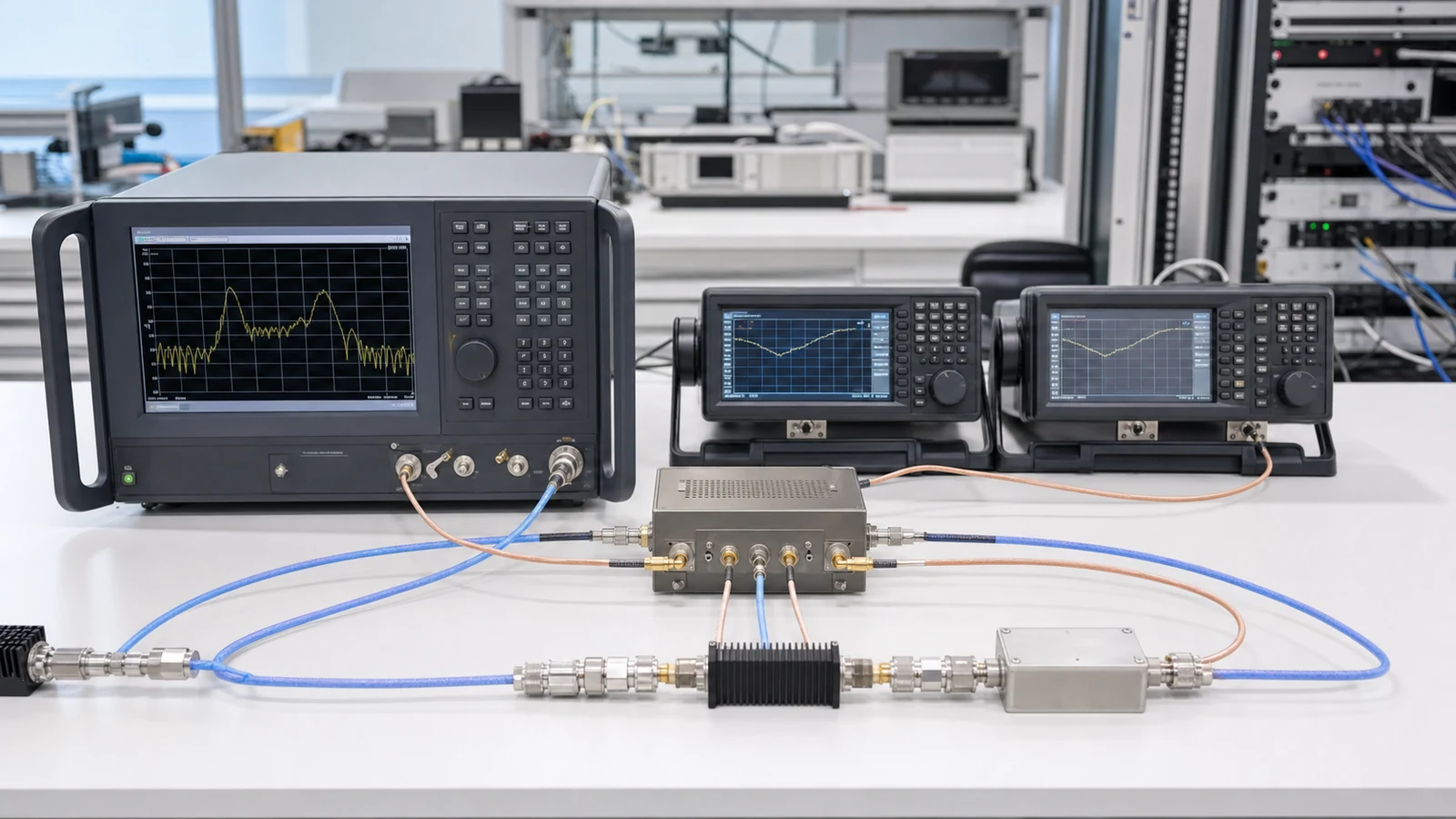
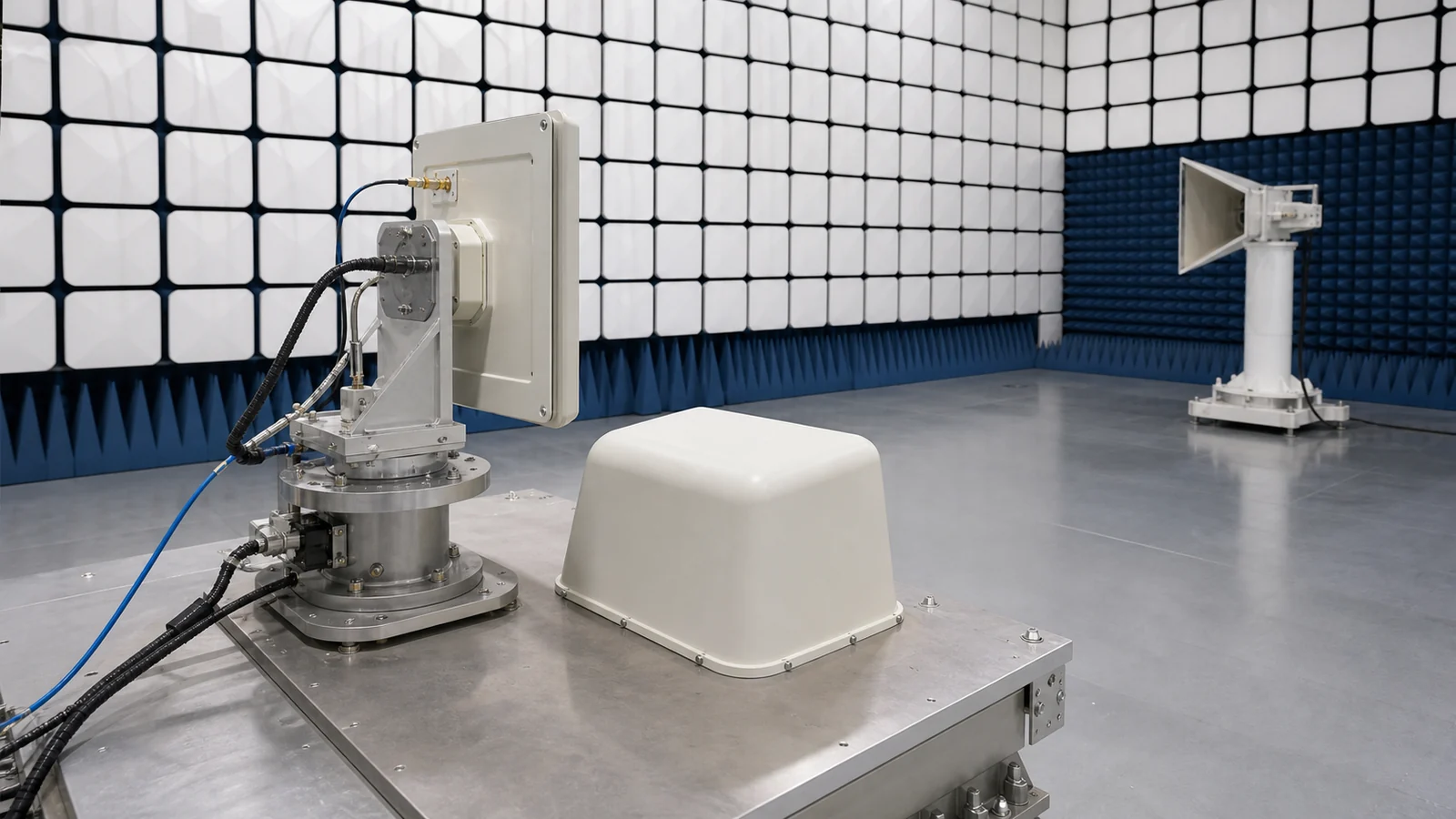
Verify component paths first, then the assembled link. Measure transmit output and spectral quality with the real waveform, receive sensitivity and blocker performance with defined wanted and unwanted signals, and switching or duplex isolation in every operating state. Confirm reference lock, startup, fault recovery and control timing. System tests should include cable and antenna paths at their installation reference planes, not only bench connectors.
- Operating bands, channel plan, bandwidth and duplex method
- Link distance, antenna interfaces and feed losses
- Transmit average and peak power, PAPR and emission limits
- Receive sensitivity, noise budget and blocker environment
- Timing reference, phase noise and synchronization requirements
- Switching states, control, monitoring and protection
- Installation, environmental and service constraints
- Bench, production and installed-system acceptance tests
Architecture and approval boundary
Communication environments and the evidence available for each project determine the RF path; no single chain fits every deployment. Hardware approval must follow the project's spectrum, waveform, link, installation and verification conditions.