Treat spectrum monitoring as an evidence chain
A weak signal is useful only if the receiver can still expose it while real strong emitters are present, visit it often enough, apply a defensible threshold and retain enough calibrated data to reconstruct the observation. The front end must therefore trade noise figure against overload margin, frequency resolution against scan time, and storage volume against evidentiary detail. Every result needs a named antenna plane, bandwidth, gain state, detector, time interval and uncertainty.
Define the monitoring mission before choosing receiver bandwidth
List the bands, channel plans, services, emission types and geographic sectors that must be observed. Separate continuous occupancy, intermittent interferers, short bursts, technical compliance checks and event capture because each needs a different relationship among instantaneous bandwidth, frequency resolution, dwell, revisit time and retention. State what decision the data must support: presence, occupancy, level, bandwidth, timing, waveform review or escalation to another system.
Describe fixed, transportable or remote operation; unattended duration; antenna height and sectors; local transmitters; expected external noise; temperature; ingress protection; network and storage limits; and the permitted response to loss of reference or storage. Do not convert a security objective into an unsupported range or classification claim. The monitoring chain can establish bounded RF observations; identification and response remain separate validated workflows.
Freeze the antenna, site and input reference plane
Specify frequency coverage, polarization, pattern, gain, antenna factor where field strength matters, cross-polar response, mast or radome, lightning and ESD protection, grounding, cable type, length and routing. An omnidirectional antenna may provide broad awareness while a directional antenna improves sector selectivity; neither has a universal range. Terrain, structure loss, antenna height, external noise and the emitter geometry belong to the scenario.
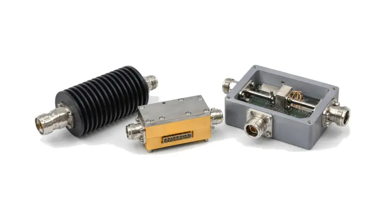
Draw every element ahead of the receiver reference plane: antenna switch, surge protector, bias network, splitter, limiter, filter, LNA, attenuator, coupler and cable. Record insertion loss, return loss, compression or survivability and control state by band. A receiver data sheet measured at its connector cannot represent the installed system if the antenna path and site environment are absent.
Allocate sensitivity and strong-signal tolerance together
Build minimum and maximum cascades in physical order. Loss before the first effective low-noise stage raises system noise, yet excessive gain can push the LNA, switch, mixer or converter toward compression. Include antenna and cable loss, preselector loss and rejection, LNA noise and gain, adjustable attenuation, receiver noise figure, input range, IP3, P1dB or full-scale boundary, AGC behavior and temperature tolerance. Specify whether the measurement uses RMS, peak, sample or detector-domain levels.
Define simultaneous signals as test vectors rather than adjectives. For each strong emitter, state frequency or sweep, waveform, occupied bandwidth, duty cycle, level and coupling plane while the weak signal is present. Verify noise-floor rise, desensitization, intermodulation, image response, reciprocal mixing, false lines, overload indication and recovery. An IP3 number is comparable only when tone spacing, level, bandwidth, gain state and test procedure are known.
Turn monitored span into a realizable coverage and revisit plan
State instantaneous bandwidth, tuning range, segment overlap, tuning step, synthesizer settling, acquisition overhead, resolution bandwidth or FFT-bin spacing, window, detector, dwell and revisit time. The frequency resolution must separate the narrowest event of interest, but reducing RBW also lowers displayed noise and usually increases observation time. A wide span and fine resolution cannot be promised at an arbitrary fast update without enough parallel bandwidth and processing.
Relate the scan plan to event duration and duty cycle. A swept receiver can pass between visits while a short burst occurs; a real-time or channelized path observes only within its instantaneous bandwidth and still has probability, trigger and buffer limits. Publish the covered bands, excluded intervals, dead time, dropped-data behavior and clock basis. Do not state probability of intercept without a defined signal duration, level, bandwidth, arrival model and receiver mode.
Define detection, threshold and recording policy as part of the RF design
Choose fixed, service-specific or adaptive thresholds according to the monitoring objective. Preserve the relationship among threshold, measurement bandwidth, noise estimate, detector, averaging, uncertainty and required false-alarm behavior. A threshold set too high hides weak events; one set too low turns noise, overload and filter leakage into occupancy. Record gain state and overload flags with every result so a raised noise floor is not mistaken for new activity.
Define what is stored: spectrum traces, channel statistics, triggered I/Q, audio, screenshots, alarm events or summary records. Include pre-trigger and post-trigger duration, sample rate, bit depth, center frequency, bandwidth, antenna and path identity, calibration state, time source, coordinates where relevant, firmware, configuration and data-integrity checks. Retention and export formats must support the intended engineering review without claiming legal admissibility.
Verify the installed chain and preserve enough evidence to repeat the result
Use a conducted path to characterize gain, noise, filters, image and spurious responses, IP3 or overload and amplitude accuracy; then repeat representative checks through the installed antenna path with known site signals or a controlled field source. Verify scanning speed, tuning accuracy, threshold behavior, trigger latency, time stamping, storage continuity, network interruption and restart. Confirm that the test source, combiner and analyzer residuals are better than the limits they are intended to measure.
Retain raw captures, source levels, cable and fixture corrections, instrument uncertainty, antenna and path identity, gain states, receiver configuration, firmware, time-reference status and pass limits. Reverify after antenna relocation, cable or protector replacement, filter or LNA change, firmware or scan-plan update, calibration expiry or any event that changes the signal path, time basis or detection policy.
| Decision boundary | Requirement to freeze | Reject the proposal when |
|---|---|---|
| Monitoring purpose | Bands, emissions, event duration, decision and required records | Only broad spectrum monitoring is stated |
| Antenna and site | Pattern, polarization, antenna factor, height, sectors, losses and local emitters | Detection range is quoted without geometry or propagation |
| Input path | Protection, cable, switching, filtering, gain, attenuation and reference planes | Receiver sensitivity is treated as installed sensitivity |
| Strong-signal state | Waveform, frequency, level, duty, coupling plane, weak signal and recovery metric | High dynamic range has no simultaneous-signal test |
| Coverage plan | Instantaneous bandwidth, RBW or bins, step, dwell, overhead and revisit | Span and update rate are quoted without dead time |
| Detection policy | Detector, averaging, threshold method, false-alarm rule and overload state | Occupancy is reported without threshold provenance |
| Recording and time | Trigger, I/Q or trace format, metadata, clock, retention and dropped-data behavior | Only screenshots or summary counts are retained |
| Acceptance evidence | Raw data, corrections, uncertainty, configuration, revisions and re-test triggers | Only a pass label or vendor data sheet is delivered |
Worked decision: more LNA gain can create phantom spectrum occupancy
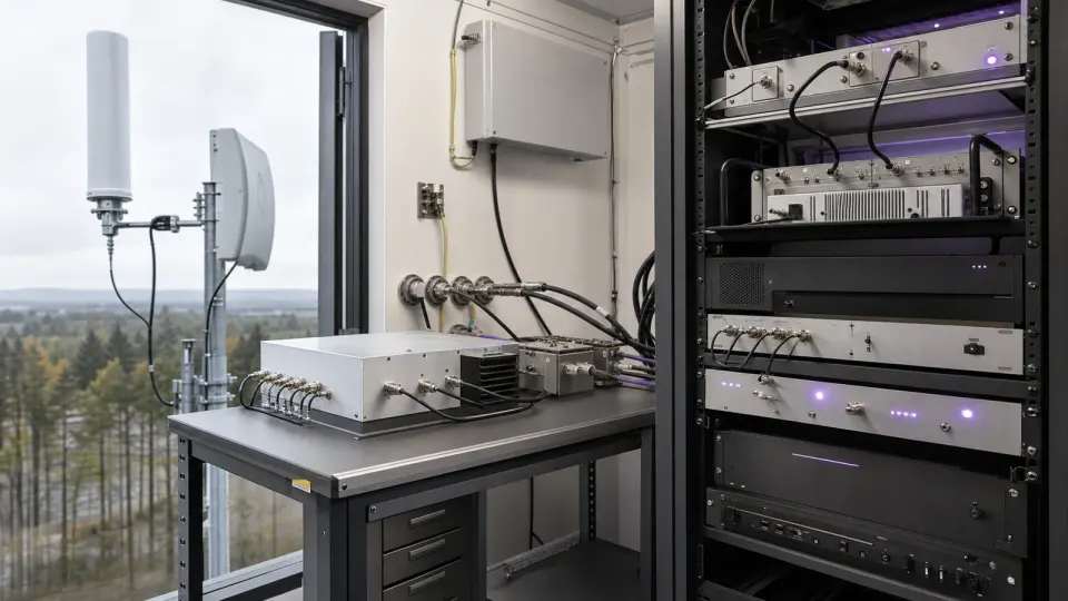
Consider a remote VHF/UHF monitoring site that must expose weak intermittent signals while a nearby cellular or broadcast transmitter remains active. Adding front-end gain lowers the receiver-referred noise floor after cable loss, but the same gain can compress the LNA or mixer, raise the apparent noise floor and create intermodulation lines. The defensible requirement sets the antenna and receiver planes, weak signal, blocker waveform and level, preselector state, attenuation or gain state, RBW, dwell, overload indication and recovery time together. Acceptance repeats the scan with and without the blocker and stores raw traces plus gain and alarm metadata; a quiet-lab sensitivity number alone would approve the wrong chain.

Verify the chain from antenna boundary to retained record
- Approve monitored bands, channel plans, emission classes, event durations and decision outputs.
- Survey antenna sectors, external noise, nearby transmitters, structures, cable route and environmental limits.
- Freeze antenna, protection, cable, switch, filter, LNA, attenuator and receiver reference planes.
- Calculate minimum and maximum loss, gain, noise, linearity, full-scale and power states by band.
- Apply simultaneous weak and strong signals with defined waveforms, spacing, levels and test-bench residuals.
- Verify preselector rejection, false responses, noise-floor rise, overload indication and recovery.
- Measure instantaneous bandwidth, tuning or scan speed, RBW, dwell, revisit time and dead intervals.
- Challenge fixed or adaptive thresholds with noise, adjacent signals, changing gain and intermittent events.
- Verify trigger, pre-trigger, recording continuity, time stamps, metadata, export and dropped-data alarms.
- Archive raw data, corrections, uncertainty, serial identity, configuration, firmware and re-test triggers.
Failures hidden by a generic spectrum-monitoring requirement
- Quoting detection range without emitter power, antenna geometry, propagation or decision threshold
- Selecting an antenna by frequency range while ignoring pattern, site noise and cable loss
- Adding low-noise gain without checking compression, IP3, reciprocal mixing or recovery
- Using one dynamic-range number without the bandwidth, gain state and test procedure
- Claiming full-band real-time coverage when only part of the span is instantaneous
- Reducing RBW without allowing the corresponding dwell, scan or processing time
- Publishing probability of intercept without event duration, arrival model and receiver mode
- Counting overload products or noise excursions as occupied channels
- Retaining traces without antenna, gain, bandwidth, threshold and time-reference metadata
- Changing the antenna path, scan plan or firmware without end-to-end re-verification
Information required for a spectrum-monitoring receiver-front-end RFQ
- Monitored frequency bands, channel plans, services and excluded frequencies
- Fixed, remote, transportable or unattended operating mode and deployment duration
- Signal types, minimum event duration, occupancy objective and required decision outputs
- Antenna polarization, pattern, gain or antenna factor, sectors, height, radome and site constraints
- Cable, protection, grounding, switching, splitter and declared system reference planes
- Minimum reportable signal and simultaneous strong-signal waveforms, levels and duty cycles
- Preselector bands, rejection, filter switching, LNA or attenuation states and control interfaces
- Noise figure, gain range, IP3, compression, full-scale, overload indication and recovery limits
- Conversion plan, image rejection, LO phase noise, spur and alias requirements
- Instantaneous bandwidth, scan span, tuning step, RBW or FFT bins, dwell and revisit time
- Detector, averaging, threshold policy, false-alarm rule and occupancy calculation
- Trace, I/Q or event recording, trigger, sample rate, bit depth, retention and export format
- Frequency, amplitude, time and location references, calibration interval and uncertainty
- Required raw data, metadata, firmware, configuration, traceability and change-control records
Continue the spectrum-monitoring engineering decision
- Review security and spectrum-monitoring applications
- Review spectrum-monitoring receiver applications
- Review receive-side signal-intelligence support
- Review RF perimeter-monitoring applications
- Review the spectrum-monitoring receiver front-end solution
- Review filtering and coexistence-chain solutions
- Read the receiver front-end characterization guide
- Send the band, signal-environment, scan and recording requirements