
LCRF

Privacy preferences

Choose optional purposes independently. You can change or withdraw your choice at any time from the footer.

Strictly necessary

Required for security, session functions and storing your privacy choice.

Always active
Preferences

Remembers optional display or language settings when these features are enabled.

Analytics

Uses first-party visitor and session identifiers to measure pages, referrals and inquiry interactions.

Marketing

Allows marketing measurement or third-party advertising technologies if they are introduced in the future.

Broadcast & RF Transmission

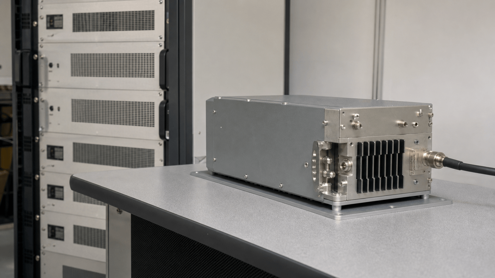
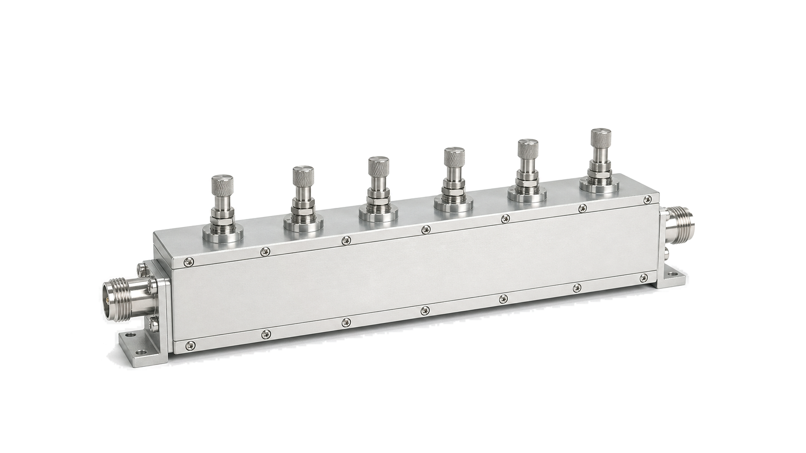
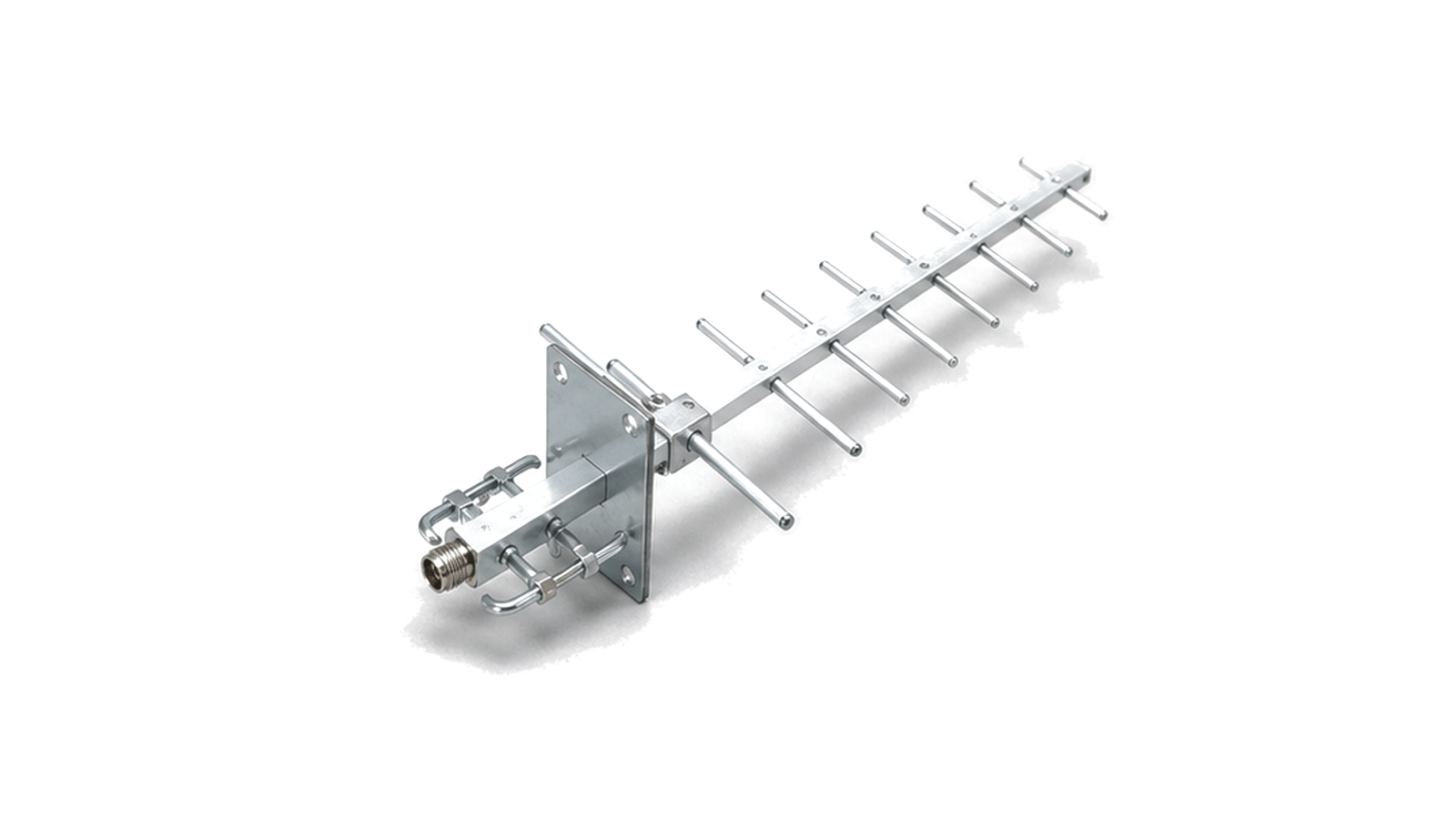
Broadcast and RF transmission systems carry scheduled or continuous RF output through transmitter chains, filters, feed lines and antenna networks.

Broadcast & RF Transmission RF application visual

Broadcast RF transmission chains

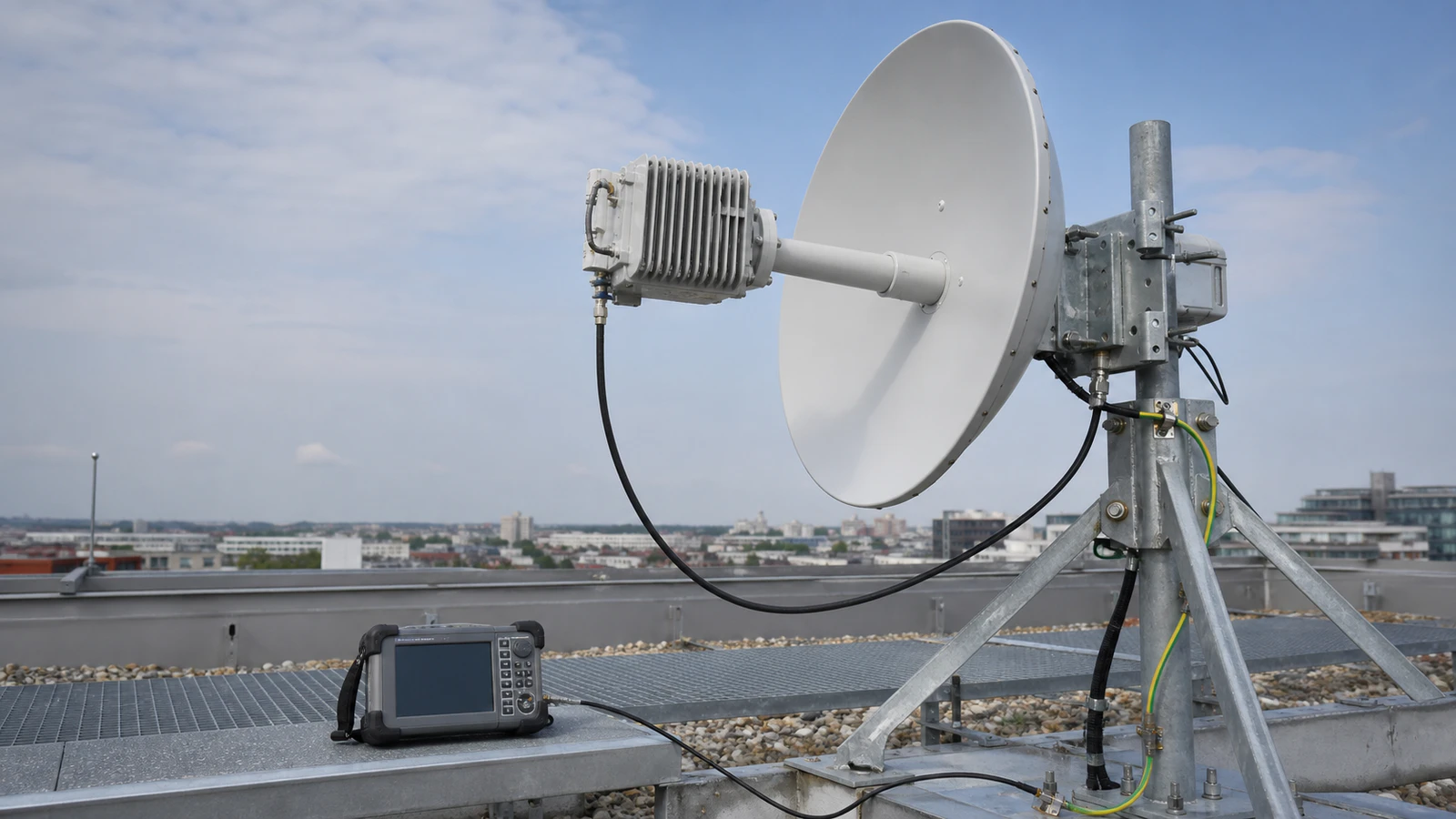
Broadcast RF transmission covers the hardware path that turns a modulated signal into controlled radiated output. It is used in broadcast transmitters, relay sites, telemetry links and fixed RF transmission facilities where the signal path must remain stable over long operating periods.

Transmission path

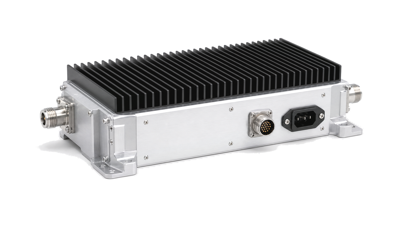
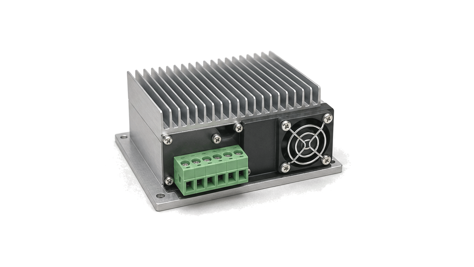
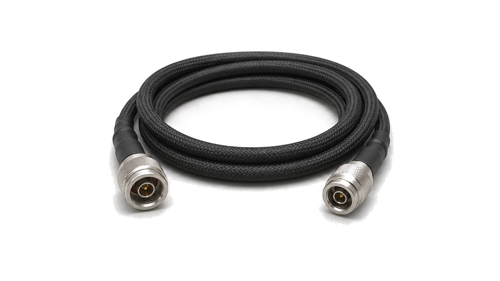
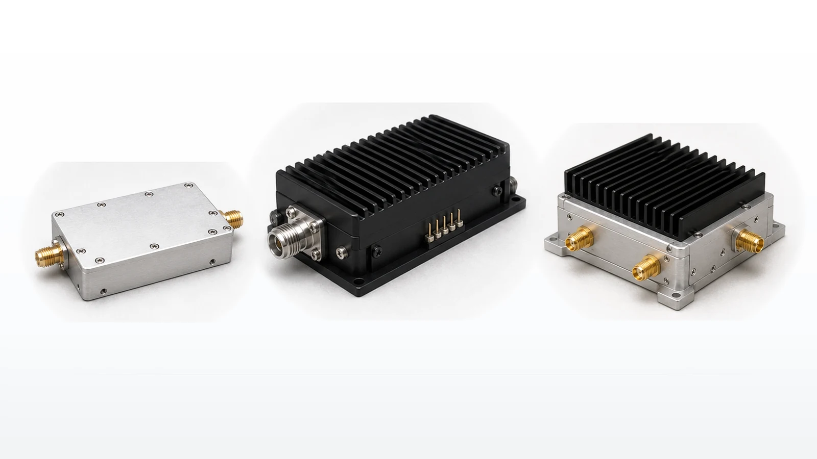
A typical path includes drive amplification, output power amplification, band filtering, coaxial or waveguide feed sections, monitoring points and the antenna interface. Power level, duty cycle, heat removal, harmonic control, reflected power and line loss shape the usable configuration.

Engineering data

Useful records include operating band, output level, modulation environment, filter response, feed-line length, connector family, antenna load condition, cooling method and protection limits for reflected power or over-temperature events.
Articles

FAQ

What thermal-interface data are needed before selecting air or liquid cooling for an RF power module?

Define dissipated heat, temperature reference, interface stack, airflow or coolant conditions and loss-of-cooling behavior before comparing cooler ratings.

How should RF filter power handling be derated for insertion loss and temperature?

Derate RF filter power from actual dissipated heat, mismatch and field stress at the declared CW or pulsed waveform, mounting and temperature, then recheck the frequency mask at equilibrium.

How do continuous-wave and pulsed operation change power-amplifier requirements?

CW selection is governed by continuous dissipation and rated output; pulsed selection additionally requires peak power, pulse width, repetition rate, duty cycle, droop, recovery and protection.

Engineering inquiry

Share your RF requirement

Share the product, operating requirements and project context. Our engineering team will route your request to the right specialist.

AttachmentsAttach drawings, BOMs, specifications or test files. Up to 5 files, 10 MB each and 25 MB total.
or drag and dropPDF, DOCX, XLSX, CSV, TXT, JPG, PNG, S1P and S2P
Typically reviewed within one business dayProject information is handled confidentially