
LCRF

Privacy preferences

Choose optional purposes independently. You can change or withdraw your choice at any time from the footer.

Strictly necessary

Required for security, session functions and storing your privacy choice.

Always active
Preferences

Remembers optional display or language settings when these features are enabled.

Analytics

Uses first-party visitor and session identifiers to measure pages, referrals and inquiry interactions.

Marketing

Allows marketing measurement or third-party advertising technologies if they are introduced in the future.

SATCOM Ground Terminal RF Hardware

SATCOM ground terminals link modem or IF equipment with antenna systems through transmit, receive, conversion, timing and feed paths. The RF chain is shaped by link budget, receiver noise, reference stability and outdoor installation.

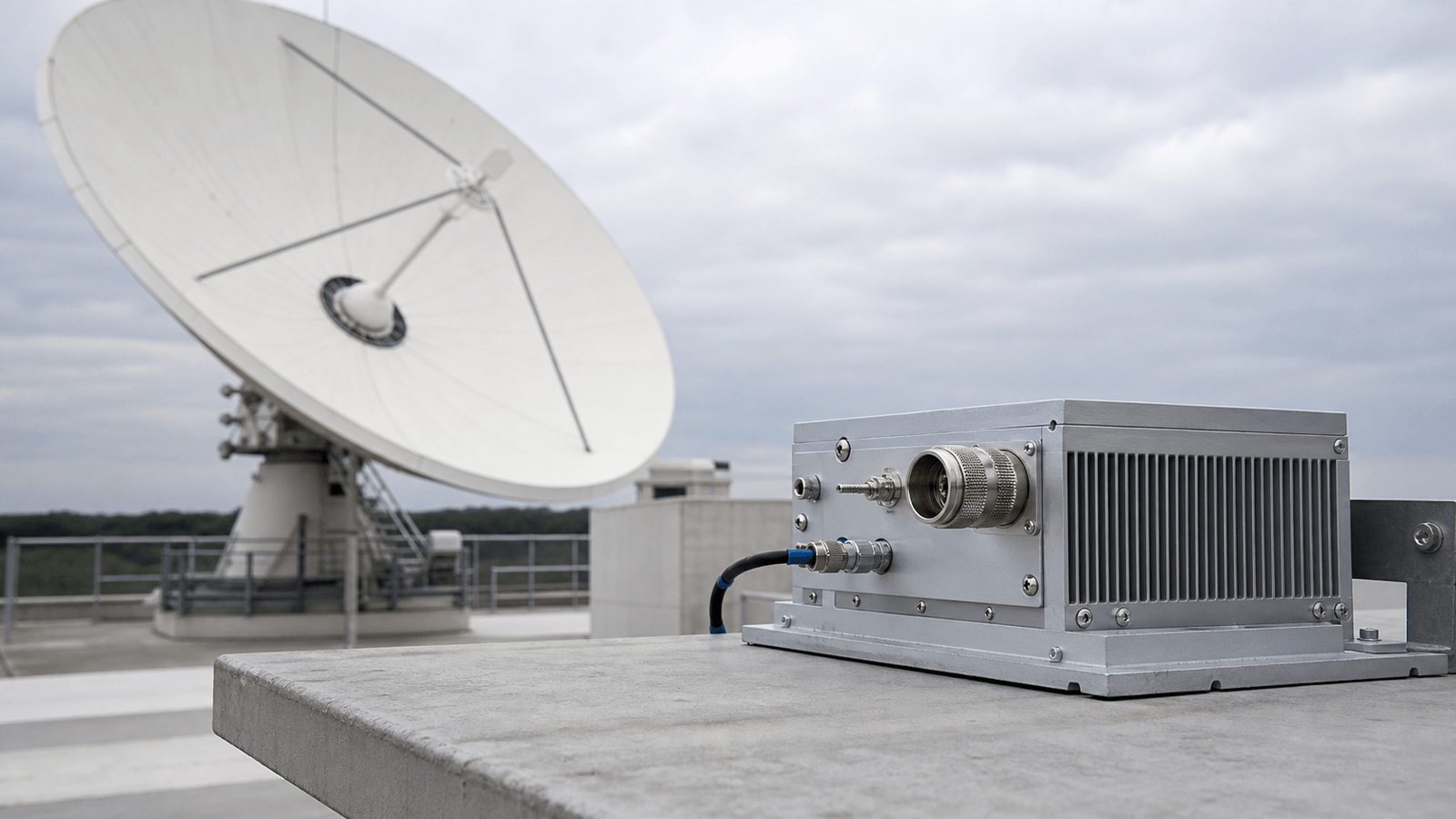
SATCOM Ground Terminals RF application visual

SATCOM ground terminal RF paths

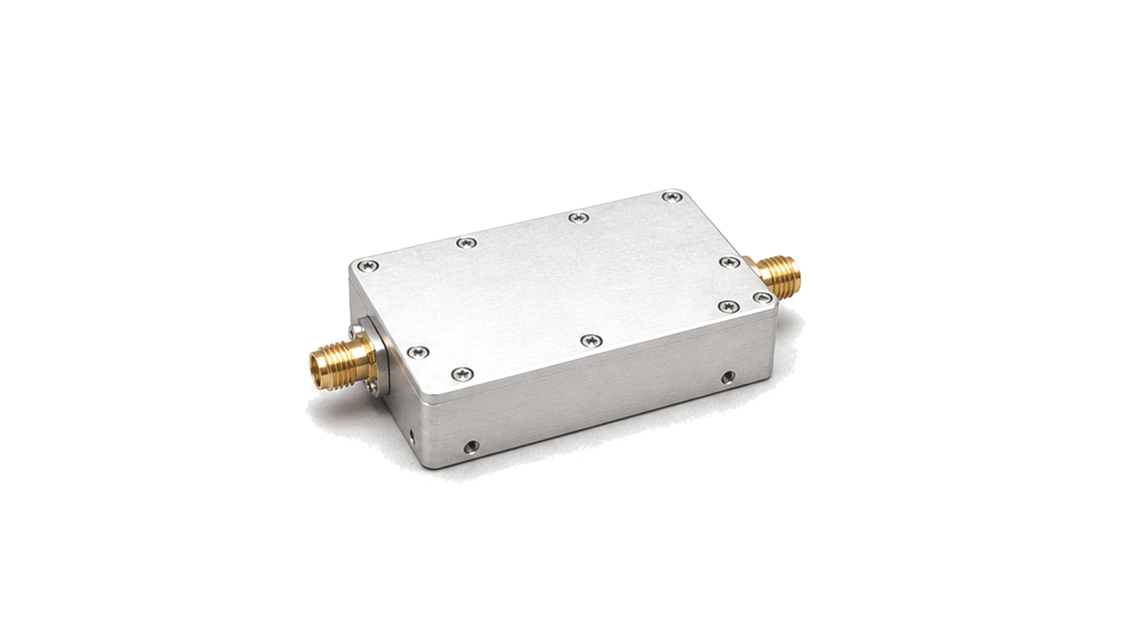
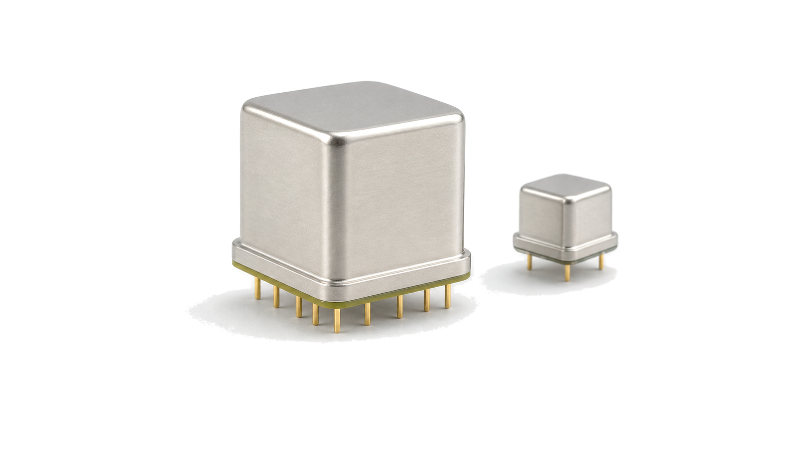
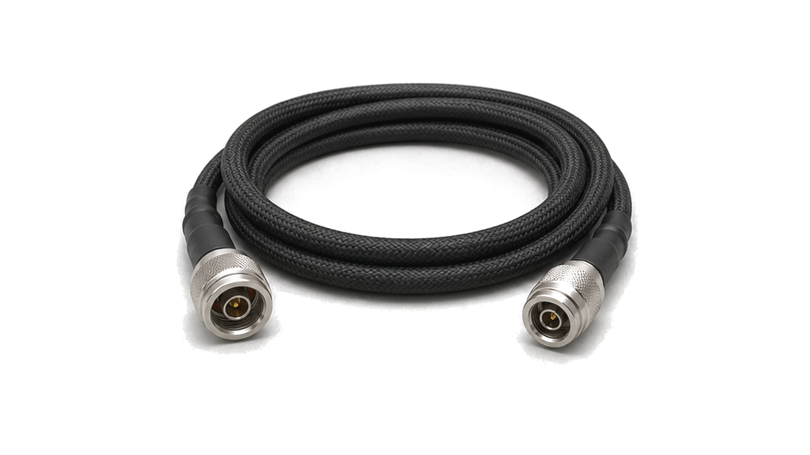
SATCOM ground terminals place the RF chain between the modem or IF equipment and the antenna system. The path may include up/down conversion, LNA stages, power amplification, filtering, OCXO reference timing, coaxial or waveguide interconnect and antenna-feed hardware.

Where it is used

Fixed earth stations, transportable terminals and vehicle-mounted SATCOM systems use this hardware to maintain uplink and downlink paths under outdoor exposure, cable loss, polarization alignment and thermal variation.

Engineering context

Relevant terminal information includes operating band, link budget, uplink power level, receiver noise, conversion plan, reference stability, feed interface, sealing and grounding. These conditions determine how individual RF modules fit into the terminal path.
Articles

FAQ

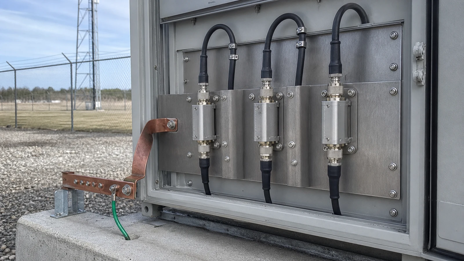
How should a coaxial RF surge protector be grounded, commissioned and retested after lightning?

Mount at the zone boundary with a short low-inductance bond, retain RF/DC/PIM baselines, inspect after an event and follow maker-defined retest or replacement limits.

Why can an installed antenna pattern differ from the free-space data sheet?

Ground planes, structures, cables, radomes and mounting tolerances change current distribution and scattering, which can alter match, gain, pattern, polarization and phase center.

How should linear, circular, axial-ratio and cross-polarization requirements be specified?

Define linear orientation or circular sense, the viewing and coordinate convention, axial ratio, cross-polar limits and the frequency and angular region where they apply.

When should GDT, quarter-wave or hybrid coaxial RF surge protection be used?

No single topology suits every installation; choose by RF bandwidth, DC continuity, maximum line voltage, residual protection target, power, PIM and service strategy.

Which RF and impulse ratings must be compared for a coaxial surge protector?

Frequency, match, loss, power, PIM and DC behavior must be checked alongside impulse waveform, current, sparkover, residual voltage and follow-current limits.

Engineering inquiry

Share your RF requirement

Share the product, operating requirements and project context. Our engineering team will route your request to the right specialist.

AttachmentsAttach drawings, BOMs, specifications or test files. Up to 5 files, 10 MB each and 25 MB total.
or drag and dropPDF, DOCX, XLSX, CSV, TXT, JPG, PNG, S1P and S2P
Typically reviewed within one business dayProject information is handled confidentially