LCRF

Privacy preferences

Choose optional purposes independently. You can change or withdraw your choice at any time from the footer.

Strictly necessary

Required for security, session functions and storing your privacy choice.

Always active
Preferences

Remembers optional display or language settings when these features are enabled.

Analytics

Uses first-party visitor and session identifiers to measure pages, referrals and inquiry interactions.

Marketing

Allows marketing measurement or third-party advertising technologies if they are introduced in the future.

Industrial & Scientific RF

Industrial and scientific RF systems use microwave energy, stable references and monitored signal paths in process equipment, instruments and research platforms.

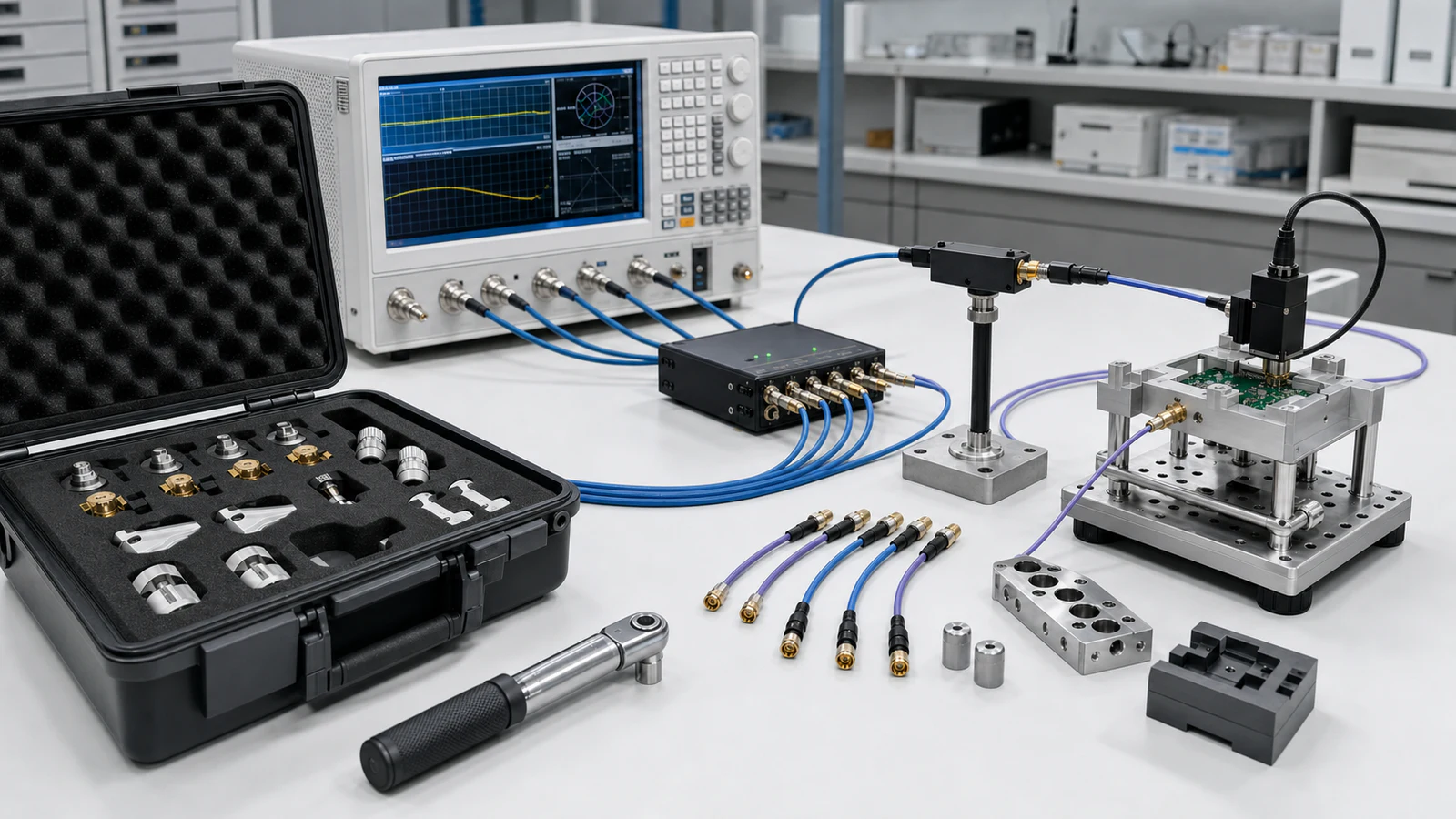
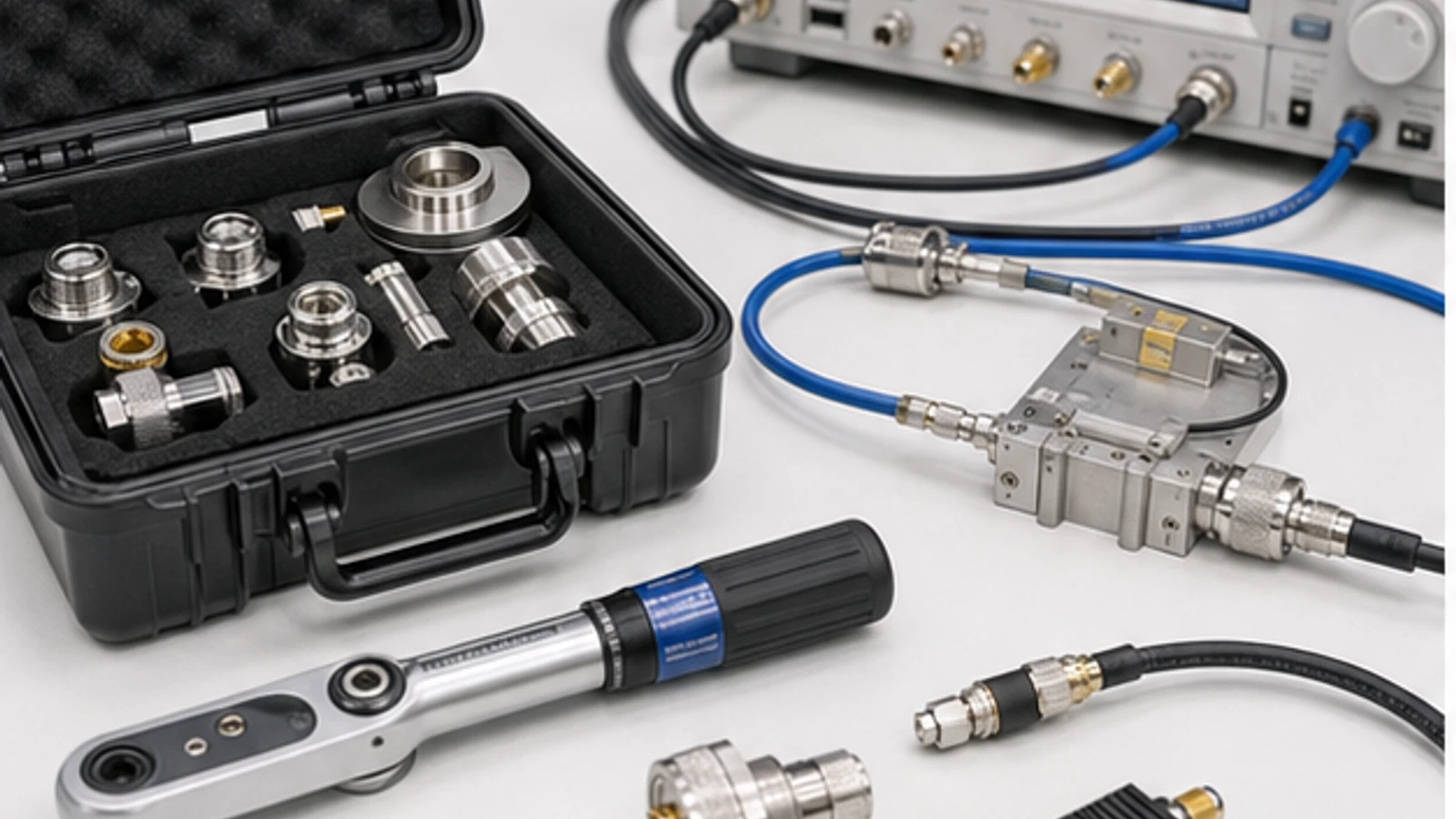
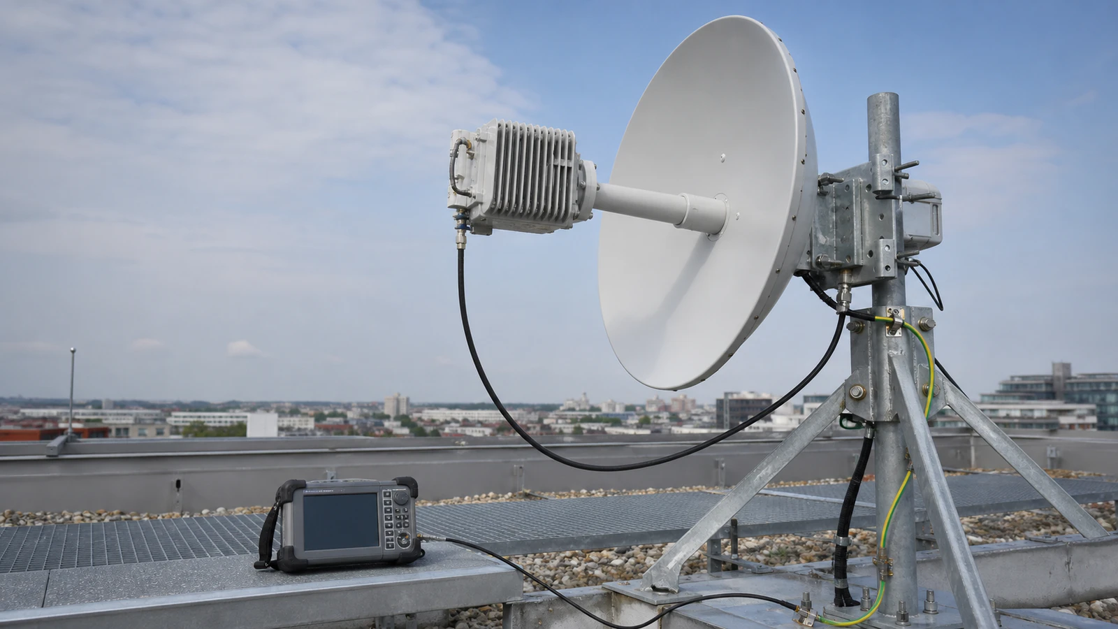
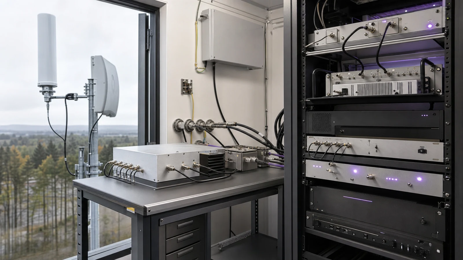
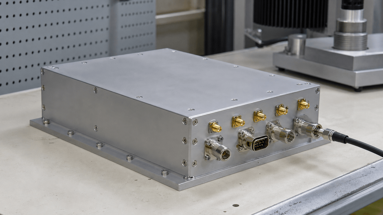
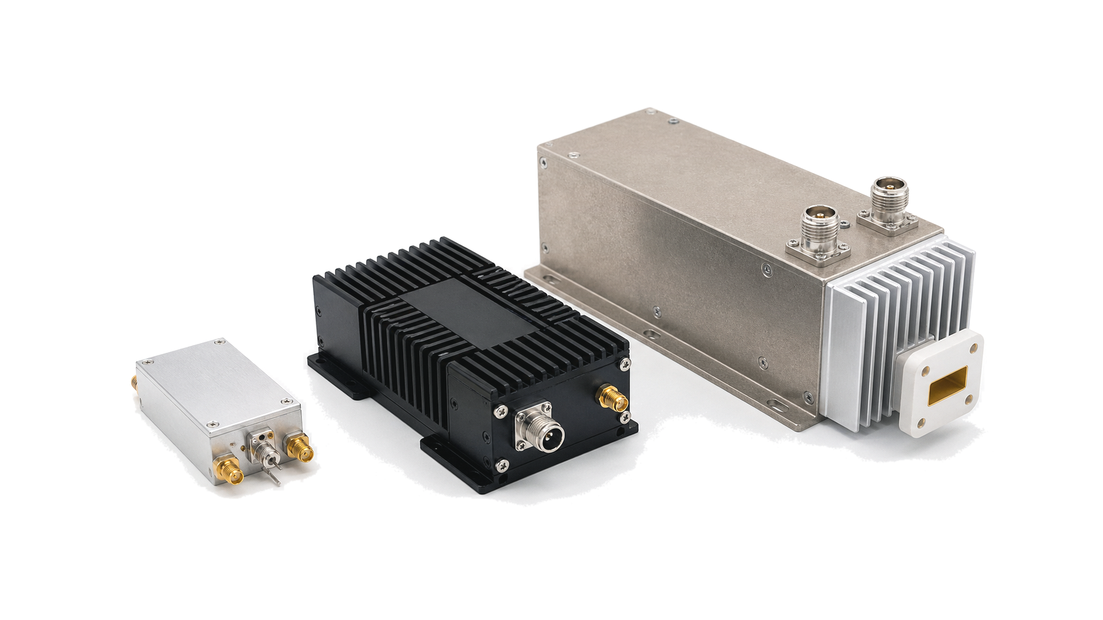
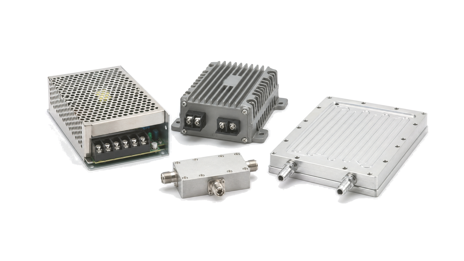
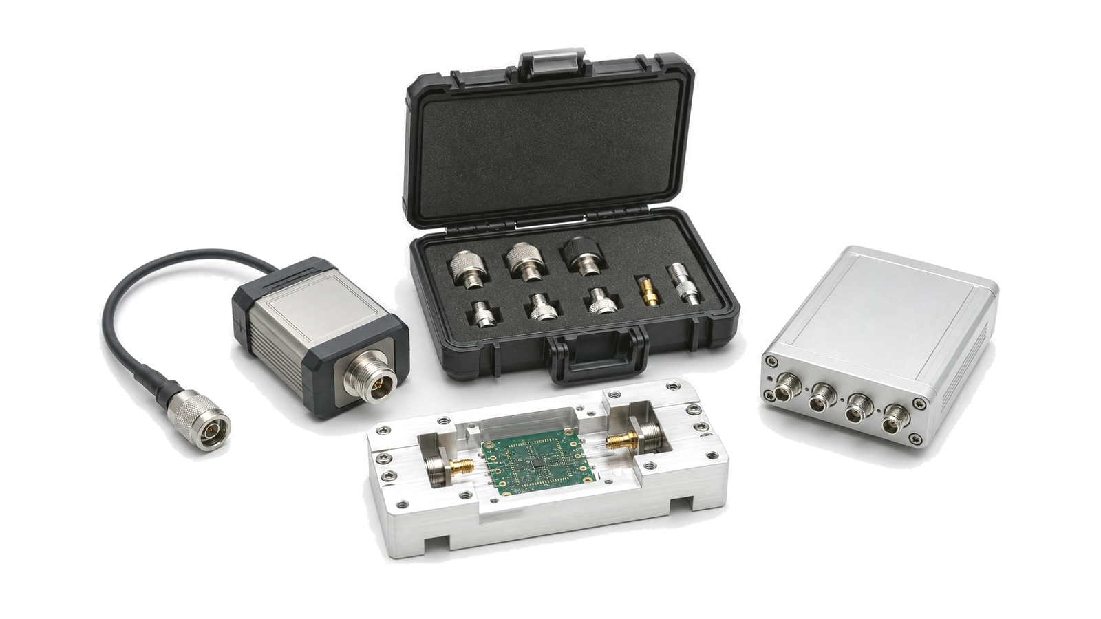
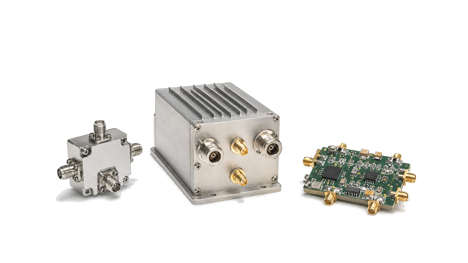
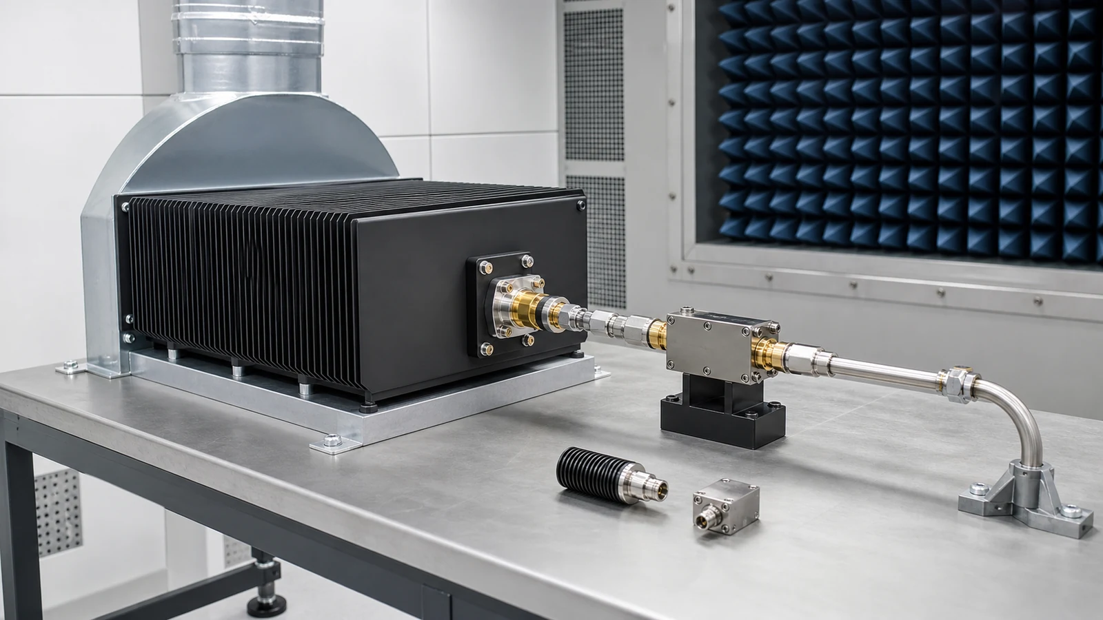
Industrial & Scientific RF RF application visual

RF hardware for process and research systems

Industrial and scientific RF work brings controlled microwave energy, reference signals and monitored RF paths into equipment that may run for long duty cycles or repeatable experiments. The hardware boundary is shaped by delivered power, frequency stability, load behavior, cooling, measurement repeatability and safe integration with control equipment.

Operating context

Typical environments include RF heating, plasma tools, semiconductor process equipment, scientific instruments, utility monitoring, robotics and laboratory RF platforms. Power stages, bias supplies, thermal paths, conversion hardware and calibrated measurement interfaces often need to remain traceable across maintenance and production runs.

RF hardware for process and research systems

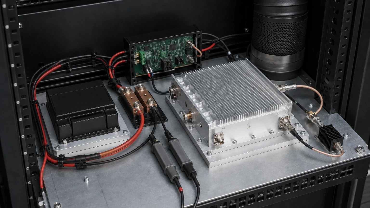
RF hardware for Industrial & Scientific RF
Operating context Typical environments include RF heating, plasma tools, semiconductor process equipment, scientific instruments, utility monitoring, robotics and laboratory RF platforms....
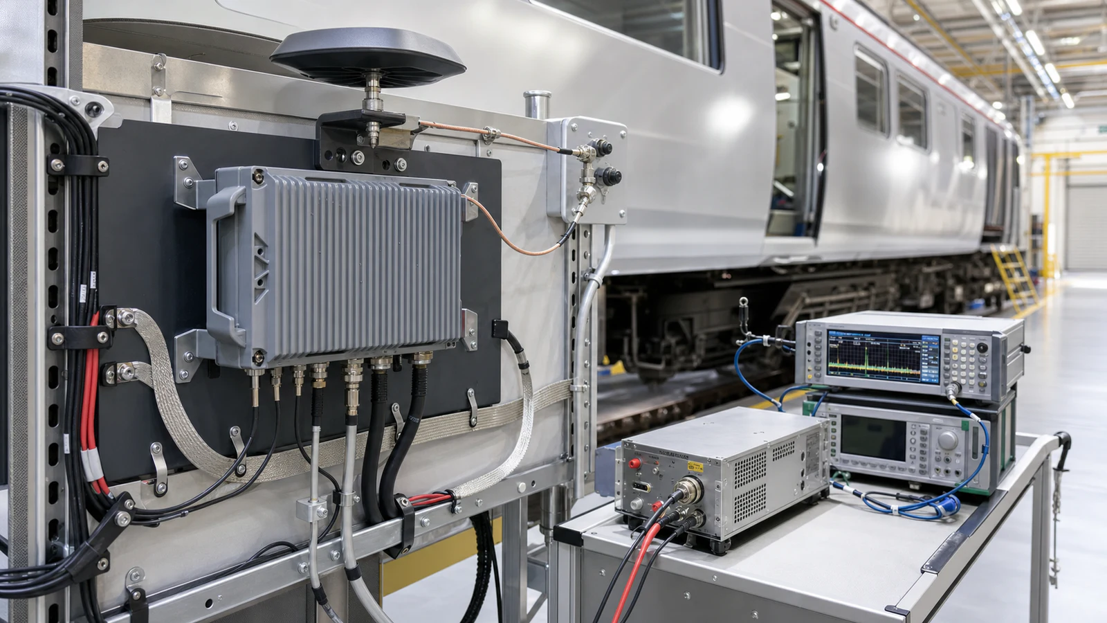
Industrial & Scientific RF RF requirements
Operating context Typical environments include RF heating, plasma tools, semiconductor process equipment, scientific instruments, utility monitoring, robotics and laboratory RF platforms....
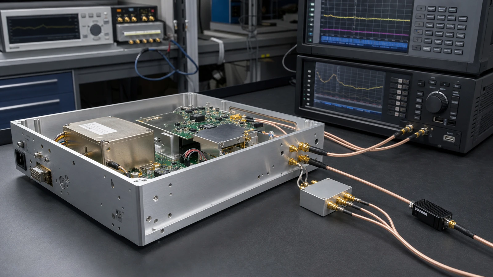
Industrial & Scientific RF RF architecture
Operating context Typical environments include RF heating, plasma tools, semiconductor process equipment, scientific instruments, utility monitoring, robotics and laboratory RF platforms....
Industrial & Scientific RF RF hardware selection
Operating context Typical environments include RF heating, plasma tools, semiconductor process equipment, scientific instruments, utility monitoring, robotics and laboratory RF platforms....
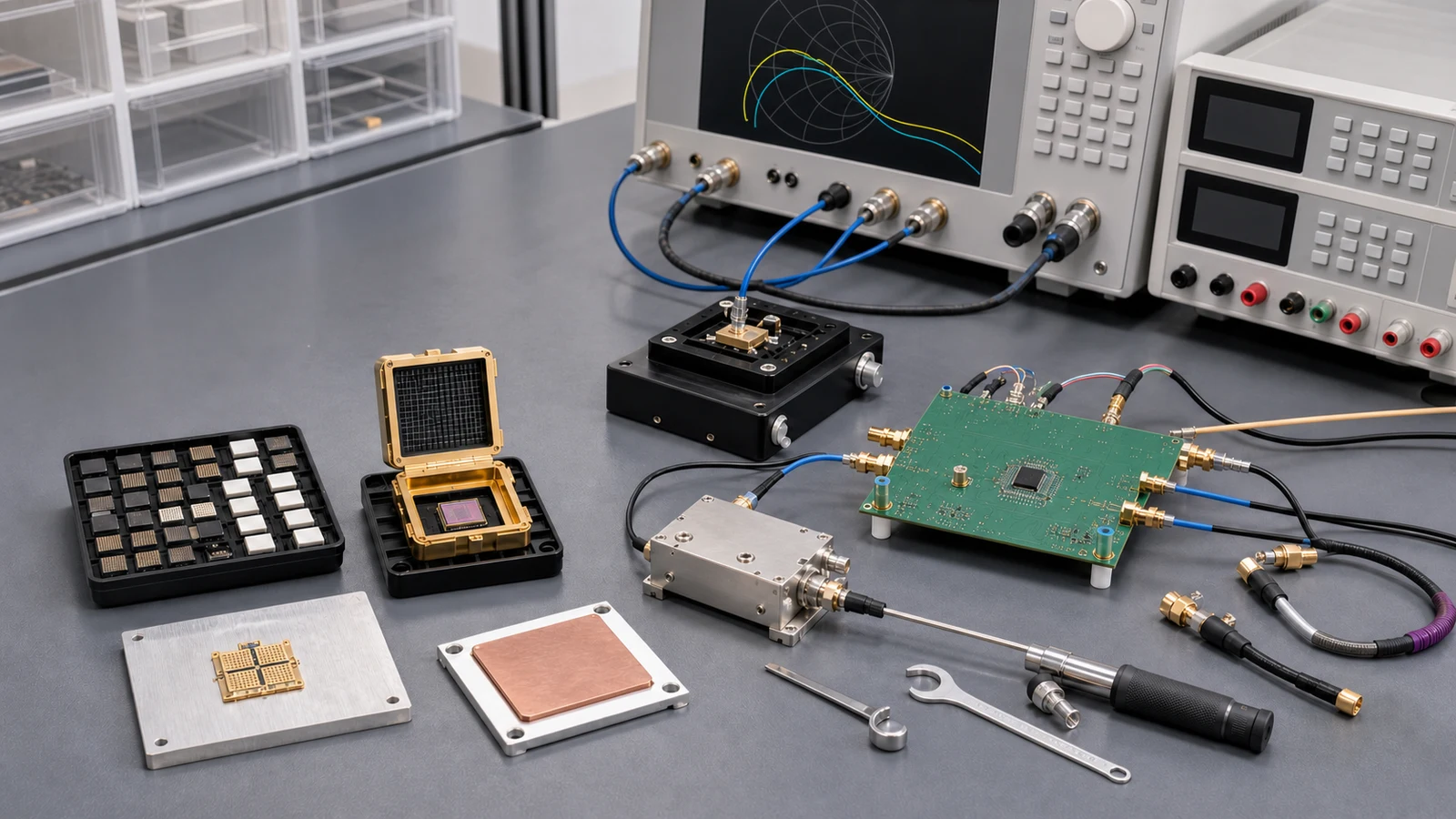
Industrial & Scientific RF RF testing and verification
Operating context Typical environments include RF heating, plasma tools, semiconductor process equipment, scientific instruments, utility monitoring, robotics and laboratory RF platforms....

Articles

FAQ

What cooling and environmental conditions belong in RF load acceptance testing?

RF load acceptance must reproduce the declared mounting, airflow or coolant, temperature, pressure and mismatch state because those conditions set electrical and thermal limits.

How should average power, peak power, duty cycle and temperature derating be specified for an RF load?

Average power predicts heating, while peak power and pulse width constrain electrical stress; both must be checked at the declared mounting temperature and cooling condition.

Why must a passive RF impedance network have a defined reference plane and complex S-parameters?

The reference plane determines where impedance and waves are defined; complex S-parameters retain magnitude and phase needed to move planes, de-embed fixtures and predict network interaction.

How are RF termination return loss, VSWR, reflection coefficient and mismatch loss related?

Return loss and VSWR express the reflection coefficient at one reference plane; reflected power and mismatch loss follow from its magnitude.

How should an RF power amplifier supply be sized for peak current, duty cycle and load transients?

Separate average and RMS heating from pulse-on current, edge-rate demand, inrush and fault current, then verify rail droop and recovery at the module terminals.

What thermal-interface data are needed before selecting air or liquid cooling for an RF power module?

Define dissipated heat, temperature reference, interface stack, airflow or coolant conditions and loss-of-cooling behavior before comparing cooler ratings.

How often should an RF test path be verified with a check standard or recalibrated?

Use both time-based intervals and event triggers, with an independent check standard that can reveal drift, cable or connector damage, switch-state change and fixture instability between full calibrations.

How much power-supply ripple and noise can an RF amplifier tolerate?

There is no universal ripple limit; derive a rail spectrum from the allowed RF spur or noise contribution and the amplifier's supply sensitivity under the real operating condition.

Engineering inquiry

Share your RF requirement

Share the product, operating requirements and project context. Our engineering team will route your request to the right specialist.

AttachmentsAttach drawings, BOMs, specifications or test files. Up to 5 files, 10 MB each and 25 MB total.
or drag and dropPDF, DOCX, XLSX, CSV, TXT, JPG, PNG, S1P and S2P
Typically reviewed within one business dayProject information is handled confidentially