How should RF hardware be planned for aerospace, defense and space programs?
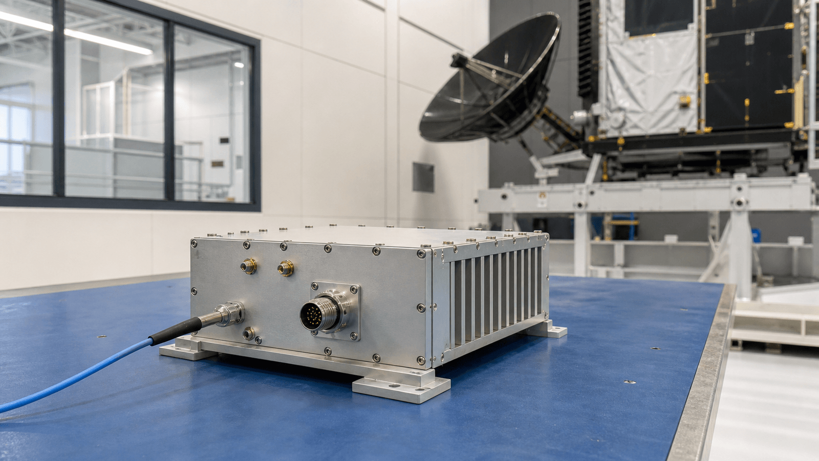
Start with the mission and life-cycle profile, define the exact hardware item and every RF, DC, timing, data, mechanical and thermal interface, then select hardware against measurable performance, environment, assurance and configuration requirements. Close the decision with a verification matrix that ties each requirement to an article, method, condition, pass criterion and delivered configuration. Airborne, ground, range and space projects may use similar amplifier, conversion, timing, antenna and interconnect functions, but they do not share one generic qualification. A replaceable ground unit, an airborne line-replaceable unit and inaccessible payload electronics face different duty, environment, maintenance and evidence expectations. The application page therefore organizes the operating contexts and procurement decisions; the detailed requirements article retains the calculation and verification workflow.
Buyer and engineering intents covered
- Aerospace, Defense & Space RF requirements: defines the mission, platform and life-cycle requirements that bound RF performance
- Aerospace, Defense & Space RF hardware selection: selects hardware by interfaces, margins, environment, assurance and evidence rather than a grade label
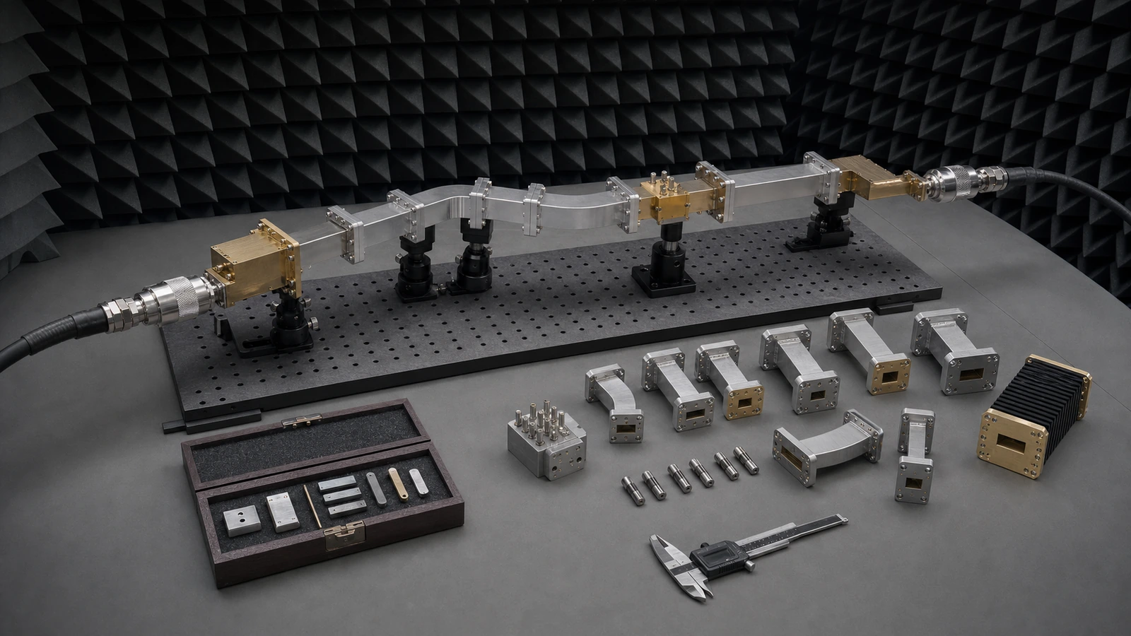
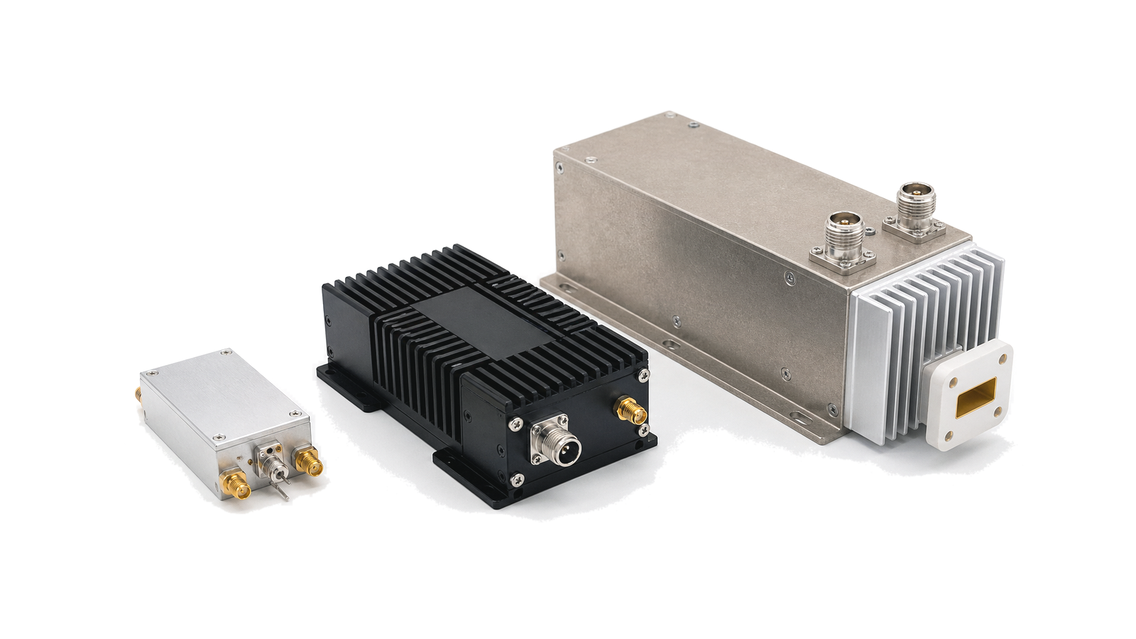
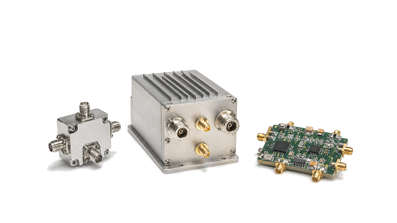
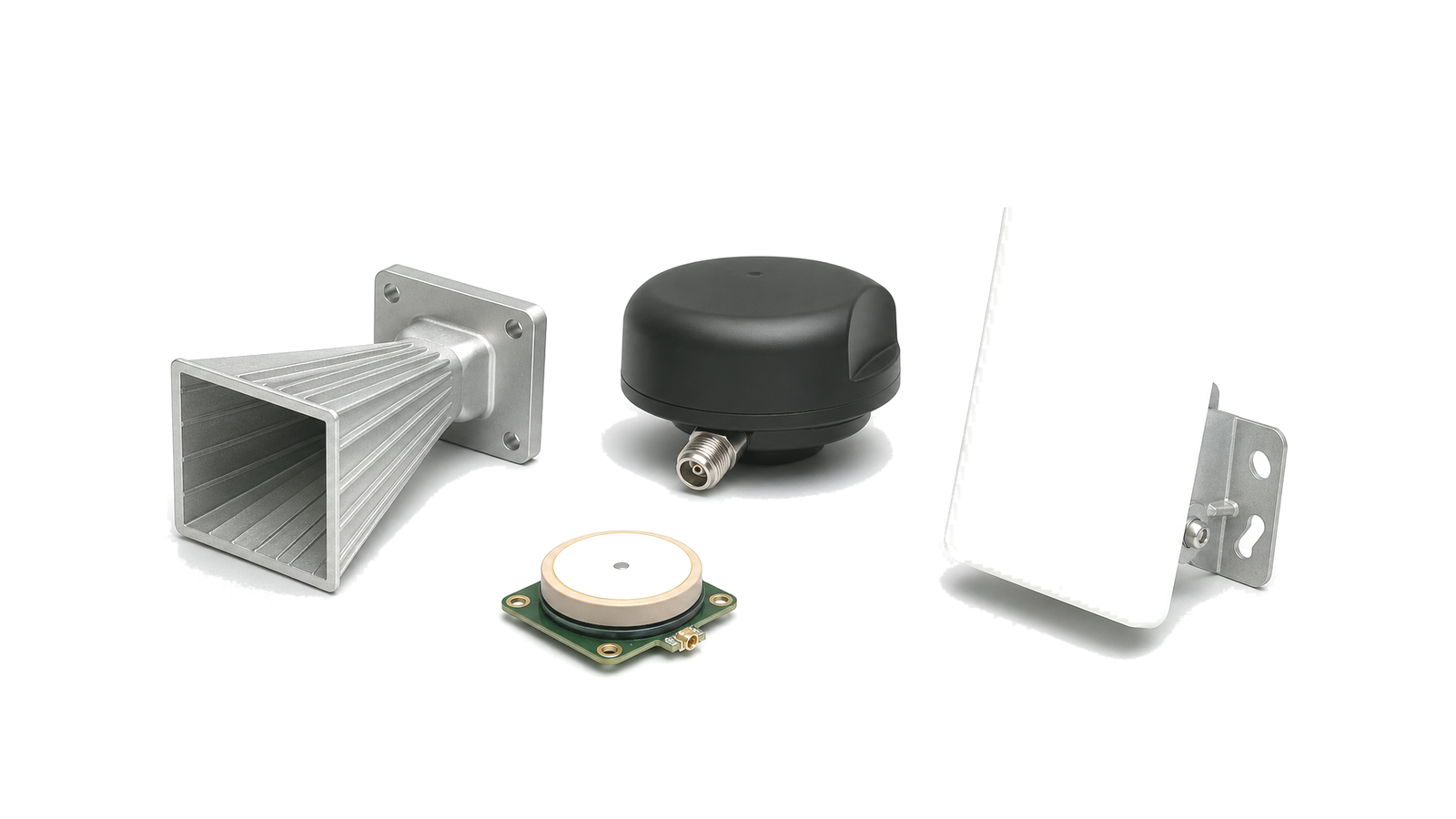
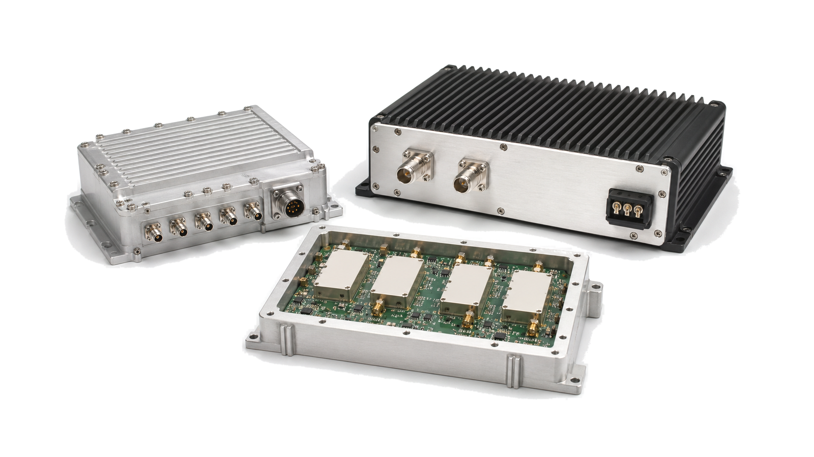
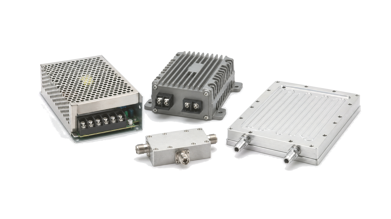
- RF hardware for Aerospace, Defense & Space: maps relevant RF hardware families into receive, transmit, timing, conversion, control and support functions
- Aerospace, Defense & Space RF architecture: builds the system architecture and assigns performance to named reference planes
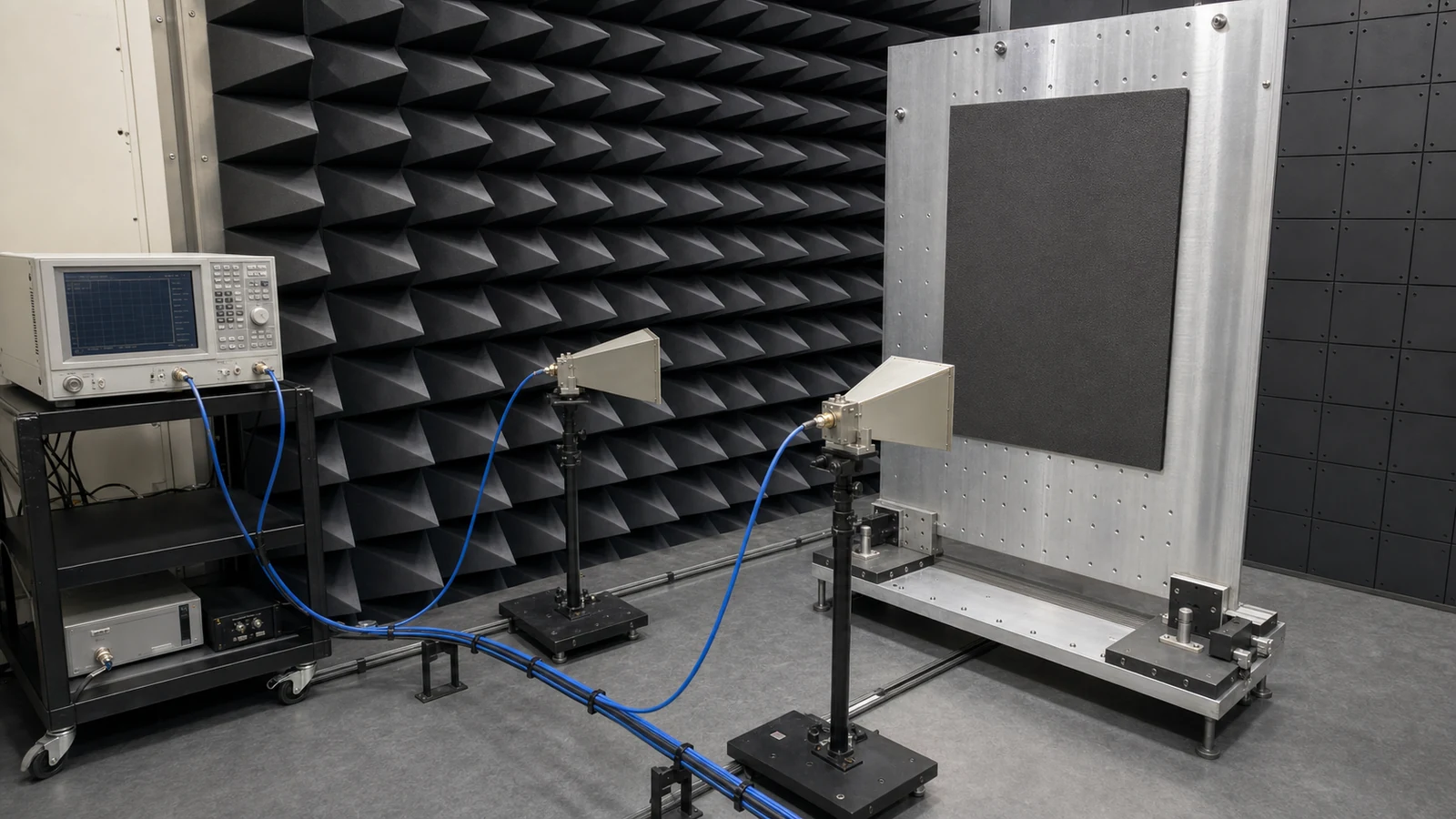
- Aerospace, Defense & Space RF testing and verification: plans qualification, acceptance and configuration-keyed verification without implying unproven approval
Choose the application path before choosing a component family
Begin with the operating context: avionics and telemetry, space payload and ground support, electronic warfare, radar or another defined mission. Record whether the item is installed, portable, ground-support, range, vehicle, airborne or orbital hardware and whether it is replaceable or inaccessible in service. This determines duty cycle, allowable maintenance, connector and packaging choices, configuration rigor and consequence of failure. The application name guides discovery; it never proves airworthiness, military qualification, radiation hardness, flight heritage or mission suitability.
Translate the mission into modes, interfaces and RF budgets
List off, standby, receive, calibration, transmit, degraded, safe and credible fault modes along the mission timeline. For each mode define active paths, frequency bands, waveform, peak and average power, gain, noise, linearity, phase, spurs, switching state, simultaneous channels and required response. Freeze RF reference planes together with power quality, timing and references, data and control, grounding and bonding, cables, cooling, mounting and mechanical datums. Allocate minimum and maximum budgets across tolerance, temperature, aging, supply and the applicable environmental effects.
Select hardware against evidence at the intended boundary
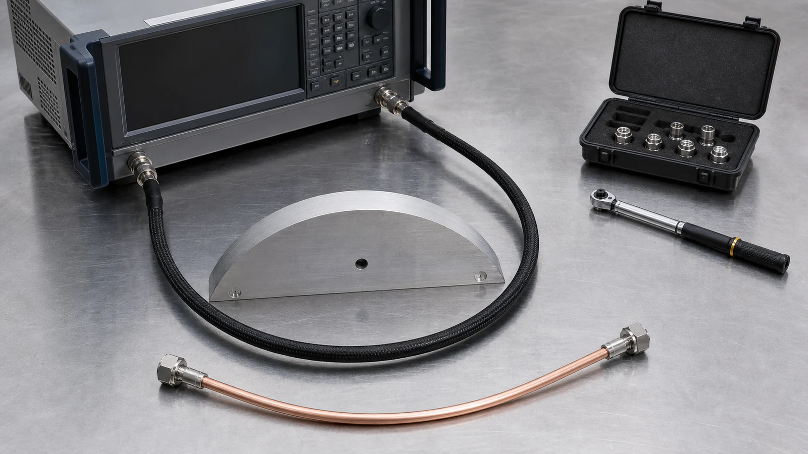
Compare amplifiers, converters, sources, filters, switches, antennas, front ends, power support and interconnect by conditions that match the planned system. Typical room-temperature values are not interchangeable with guaranteed limits, installed-chain performance or qualification evidence. Ask which revision, lot, test plane, fixture, waveform, baseplate or airflow, software and calibration produced each result. Parts class or rugged labels cannot replace a reviewed component, materials, derating, supply-chain and workmanship plan.
Tailor environmental and assurance requirements to the life cycle
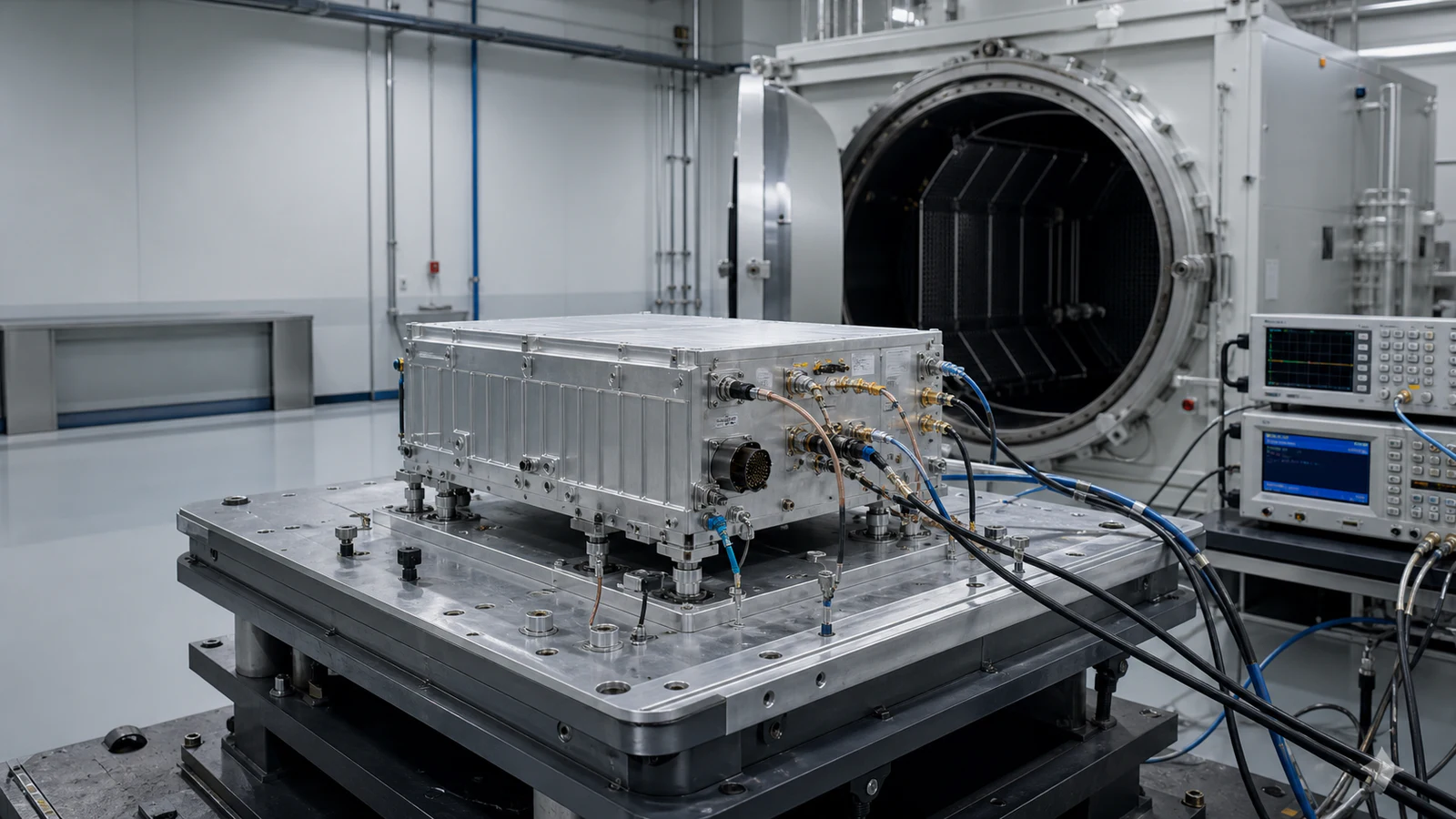
Map storage, handling, transport, launch or flight, vehicle, outdoor, ground-station and orbital exposure before selecting methods. Define temperature, pressure or vacuum, humidity, shock, vibration, acoustics, acceleration, contamination, EMC and radiation only where the program profile supports them. State axis, level, spectrum, rate, duration, operating mode, monitoring and pass criteria. Separate survival from operation and retained RF performance. The applicable authority and project documentation control tailoring; a standard number alone is not a universal certification.
Plan verification, article pedigree and configuration control together
Give each shall requirement a source, method, level, test article, configuration, condition, margin and acceptance criterion. Distinguish breadboard, engineering, qualification, protoflight, acceptance and service hardware. Record fixtures, adapters, cable correction, uncertainty, calibration, raw results and anomalies. Baseline drawings, BOM, approved sources, firmware, calibration coefficients, deviations and serial or lot identity before evidence is accepted. A change to a device, board, filter, cable, interface material, enclosure, cooling path or software threshold requires an impact decision and possibly re-verification.
Send an RFQ that can be evaluated without guessing
The inquiry package names the item boundary, platform context, mission modes, life and maintenance concept; RF and platform interfaces; guaranteed and target performance; environmental and assurance tailoring; quantity and schedule; required article pedigree; verification, acceptance and reporting; configuration, notification and substitution rules; and delivery data. Mark unknowns explicitly and request an assumption log. This lets the engineering review distinguish an available hardware family, a configurable assembly and a project-specific development path without overstating current evidence.
Application decision matrix
| Decision area | Define before selection | Evidence required |
|---|---|---|
| Mission and item | Platform, phases, modes, service life, maintenance and exact item boundary | Approved mission profile and requirement baseline |
| RF architecture | Reference planes, bands, waveform, power, noise, linearity, phase and margins | Budget and interface control linked to configuration |
| Environment | Life-cycle stresses, operating state, monitoring and pass criteria | Tailored verification plan and article pedigree |
| Assurance | Parts, materials, workmanship, derating, source and change rules | Configuration records, traceability and approved deviations |
| Acceptance | Methods, limits, uncertainty, data format and delivery set | Raw results, report, calibration and disposition |
RFQ inputs for aerospace, defense and space RF hardware
- Exact item, platform context, installation and maintenance boundary
- Mission phases, operating modes, duty cycle, storage and service life
- RF bands, waveform, power, gain, noise, linearity, phase and spectral limits
- RF, DC, timing, data, control, grounding, cooling and mechanical interfaces
- Temperature, pressure, humidity, shock, vibration, EMC and radiation tailoring
- Parts, materials, sourcing, lot traceability, derating and workmanship expectations
- Configuration baseline, firmware, calibration, deviations and substitution rules
- Qualification, acceptance, article pedigree, facilities and pass criteria
- Quantity, prototype and production schedule, spares and support assumptions
- Required reports, raw data, certificates, drawings, index and change notifications
Evidence boundary
The application scope organizes mission environments, architecture, hardware-family selection and evidence planning. Qualification, radiation tolerance, airworthiness, platform approval, flight heritage, export status and mission performance are never inferred from a category relationship or generic description; each remains dependent on the exact product or project record and the responsible approval authority.