What must a radar, EW or Counter-UAS RF system definition resolve?
It must connect the mission mode and electromagnetic environment to measurable waveform, timing, channel, receive, transmit, isolation, control and verification requirements at named antenna and equipment reference planes. Radar, electronic-warfare and UAS-detection paths may share antennas, converters, amplifiers, switches and monitors, but they do not share one universal budget. Search, track, classify, direction-find, record and response-support modes expose different combinations of noise, instantaneous bandwidth, pulse density, coherence, latency and power.
Engineering work packages covered
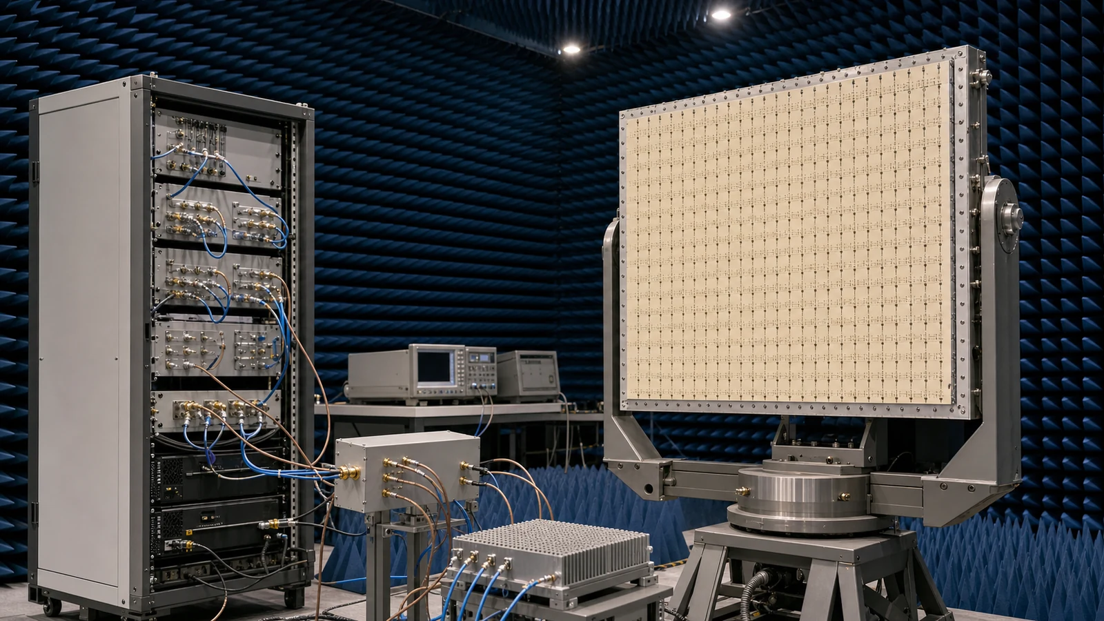
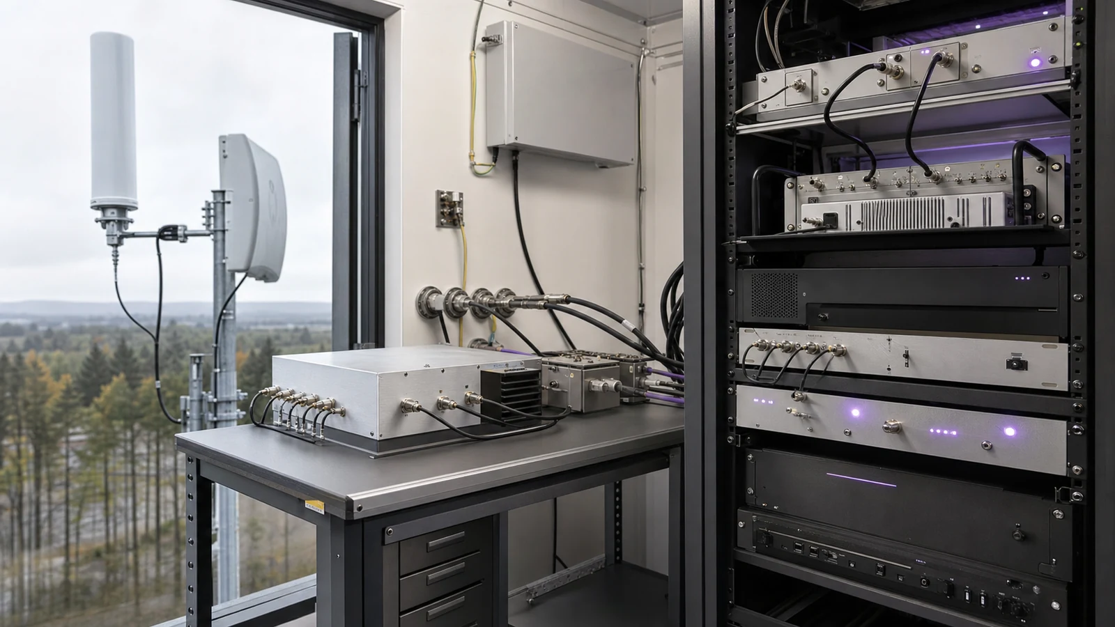
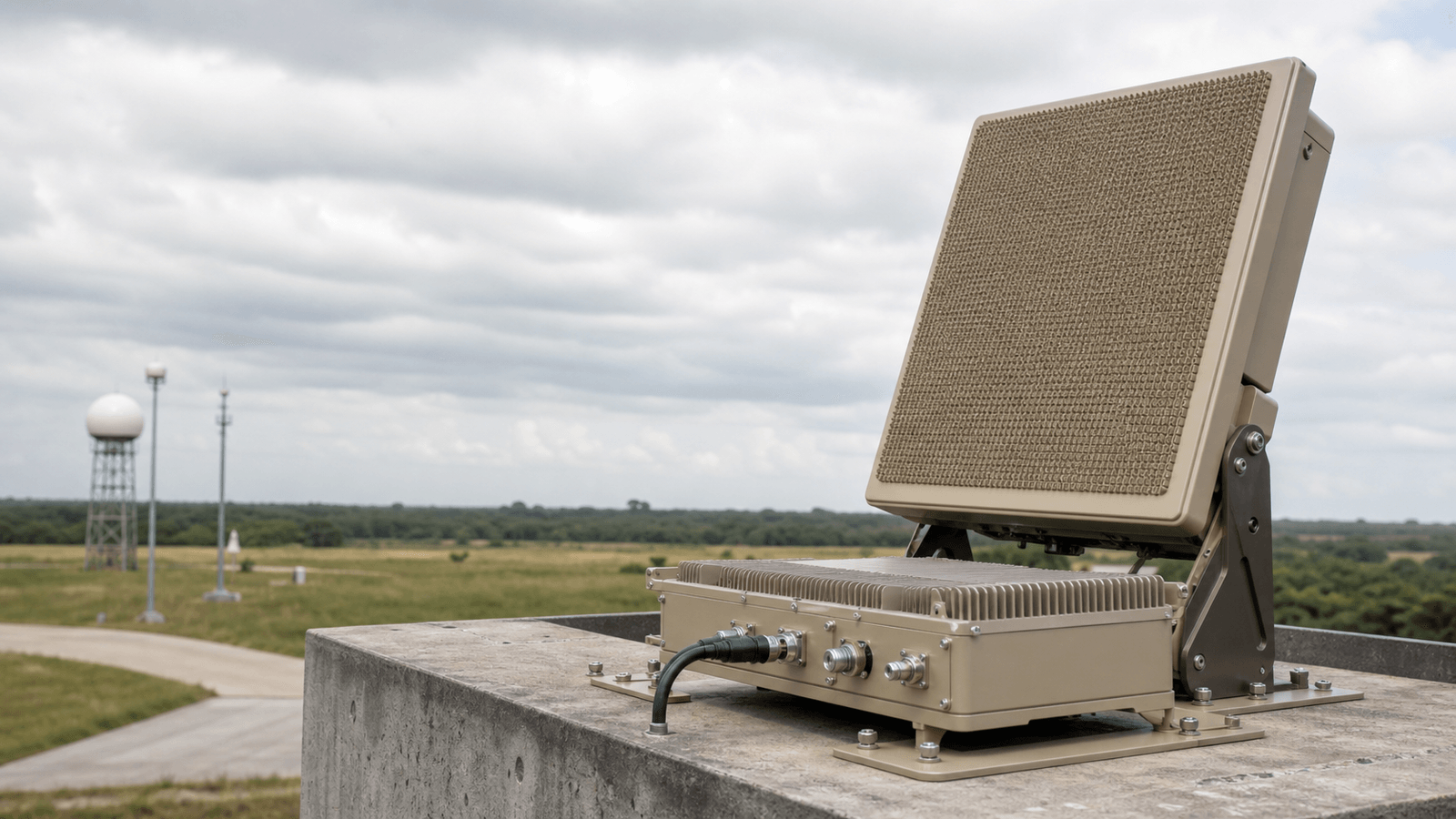
- Radar, EW and Counter-UAS RF Systems architecture: maps sensing, warning, direction-finding and response-support modes to antennas, coherent channels, conversion, gain and switching
- Radar, EW and Counter-UAS RF Systems design requirements: turns frequency coverage, pulse or modulation behavior, dynamic range, timing and environment into block-level allocations
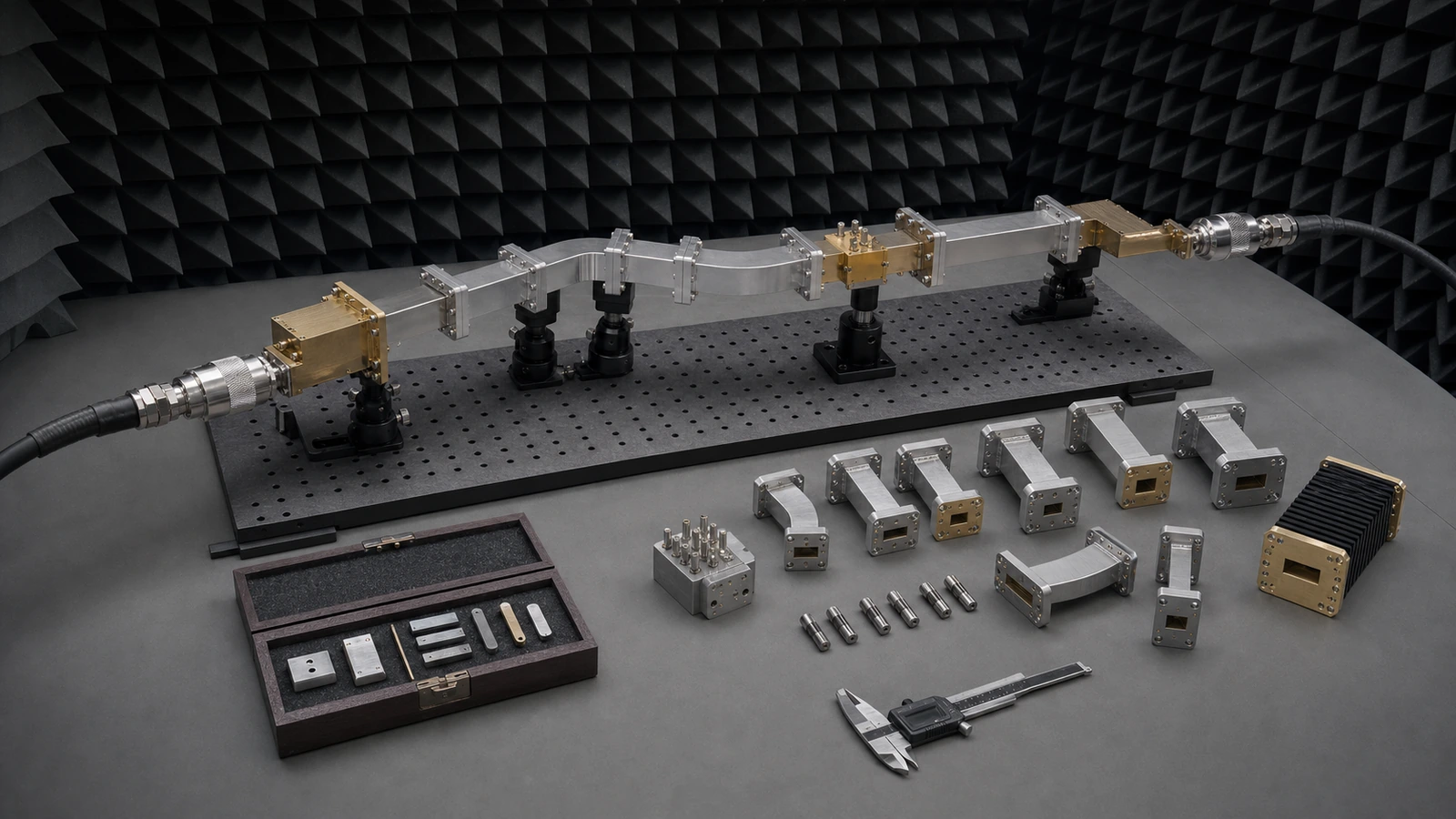
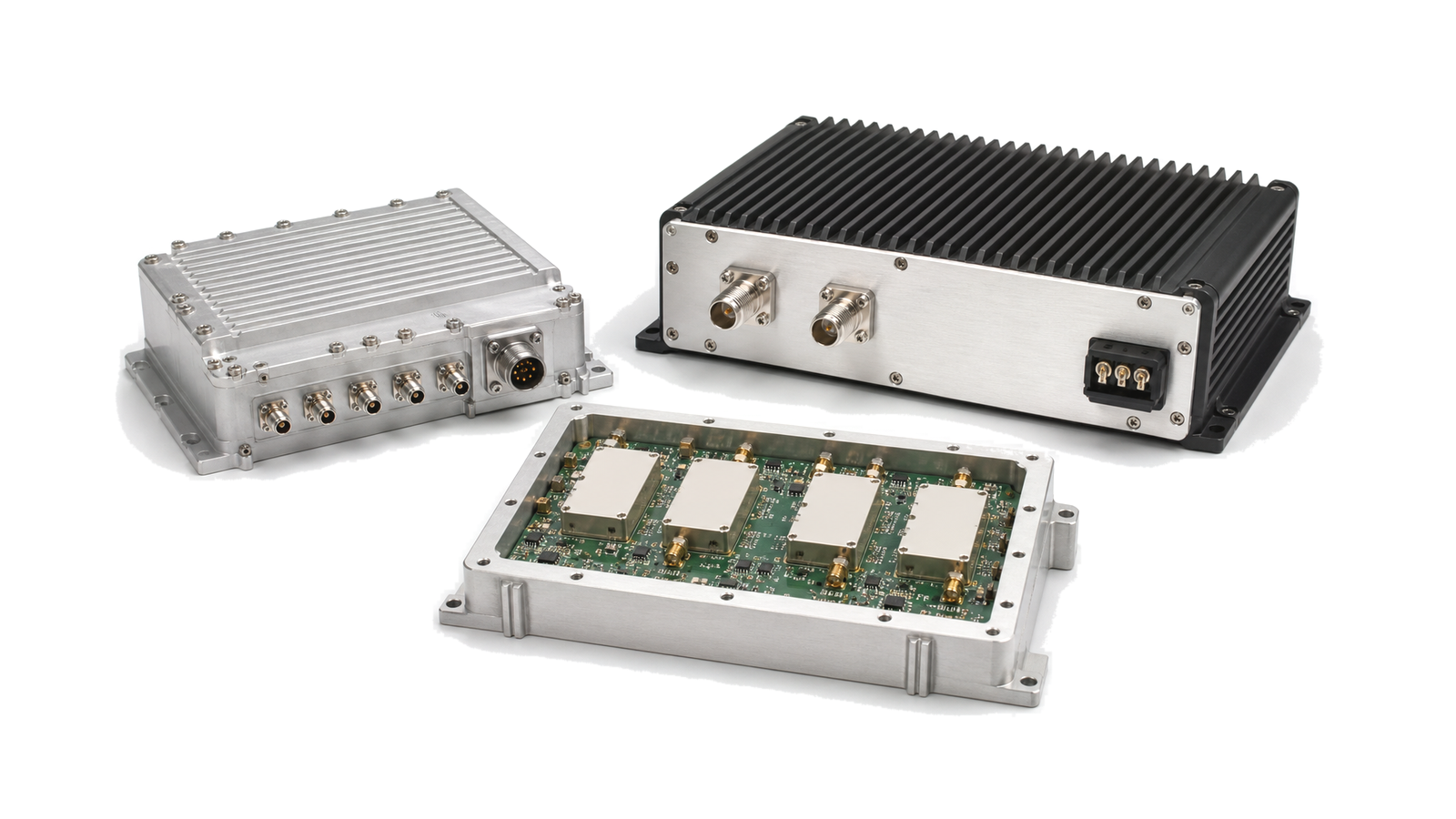
- Radar, EW and Counter-UAS RF Systems integration: aligns RF, clock, digital control, calibration, power, thermal and mechanical interfaces across channels
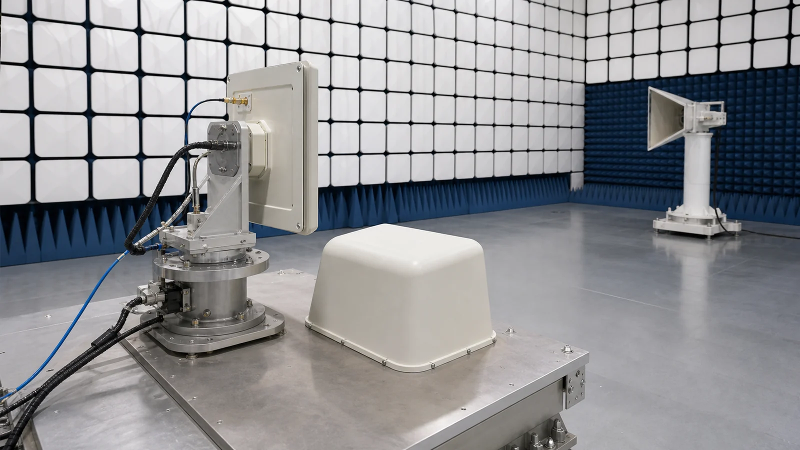
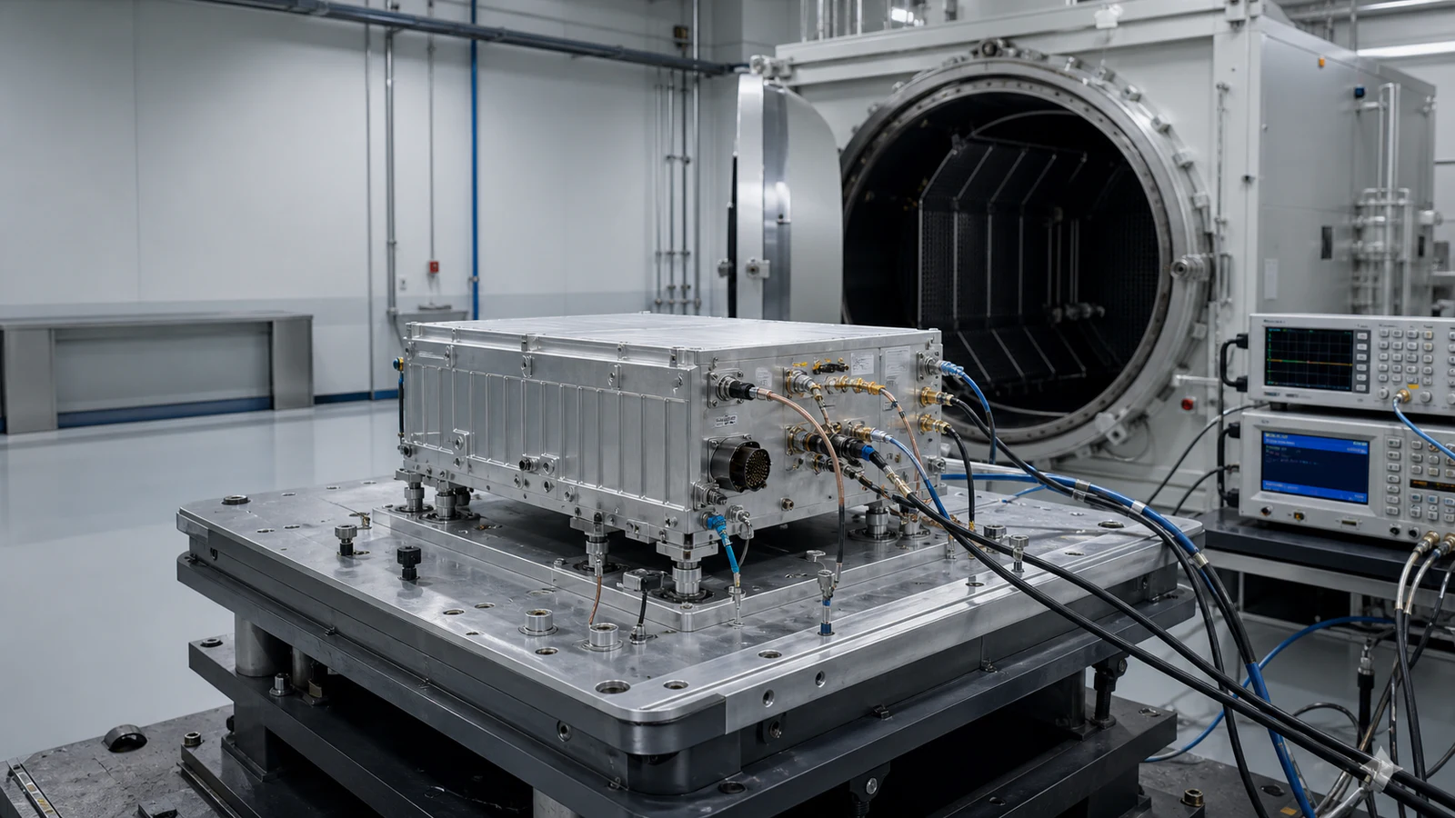
- Radar, EW and Counter-UAS RF Systems test and verification: proves calibrated pulse, phase, amplitude, sensitivity, recovery, isolation and scenario performance before field deployment
Freeze the mission modes and RF reference planes
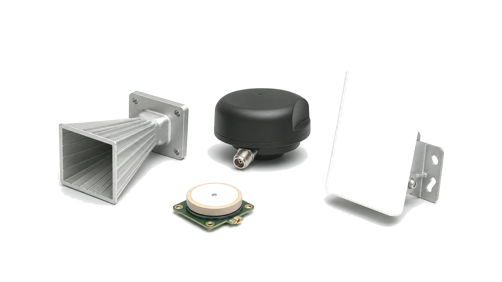
List each required mode: surveillance, tracking, target illumination, radar warning, electronic support, recording, direction finding, UAS detection or authorized response support. For each mode, name antenna ports, polarization, beam or sector, simultaneous channels, transmit/receive state, tuning range, instantaneous bandwidth and latency. Separate conducted connector planes from array or radiated planes. A receiver sensitivity measured after a gain block cannot be compared with field detection performance until antenna, propagation, polarization, scan and processing assumptions are explicit.
Control waveform, timing and channel coherence
Define carrier range, pulse width, PRI or PRF, burst structure, chirp or phase coding, modulation-on-pulse, rise and fall time, duty cycle and allowable frequency or phase error. Multi-channel receivers and arrays need a common time and frequency reference plus limits for relative amplitude, phase, group delay and trigger skew. Direction-finding and beamforming performance depends on calibration stability across frequency, level, temperature and reconfiguration, not merely on sharing the same 10 MHz clock.
Close receiver sensitivity and instantaneous dynamic range
The receive path may include antenna or array, duplexer or T/R switch, limiter, preselector, LNA, conversion, IF gain and digitizer. Allocate noise figure, gain, input P1dB, IP3, image and spur rejection, ADC headroom and recovery after a large pulse. Evaluate in-band pulse density, simultaneous emitters, local transmit leakage, clutter and out-of-band blockers. A chain that meets small-signal sensitivity but remains blind after leakage or limiter recovery does not meet the mission state.
Specify pulse and modulated transmit performance
Translate range or effect requirements into linear power at the antenna plane, then allocate power amplifier output, feeder loss, antenna gain, waveform back-off and duty cycle. Measure peak and average power, pulse droop, overshoot, rise and fall time, pulse-to-pulse amplitude and phase stability, chirp linearity, EVM where relevant, harmonics, spurs and spectral occupancy. Include mismatch exposure, reflected-power action, thermal accumulation, blanking, inhibit and safe-state timing.
Design isolation, routing and calibration into the architecture
Define port-to-port, channel-to-channel and transmit-to-receive isolation for every switch state. Couplers, detectors, calibration injection, loopback paths and built-in test points need known directivity, level and reference plane. Control data must identify configuration, frequency, gain state, beam or channel, time tag and fault status. For arrays or distributed sensors, cable and module phase must be traceable through replacement, temperature cycling and maintenance.
Verify in realistic but controlled electromagnetic scenarios
Begin with calibrated S-parameters, noise, compression, pulse, phase-noise and channel-match measurements. Then exercise the assembled path using repeatable single- and multi-emitter scenarios across frequency, pulse density, amplitude, angle-of-arrival cues, delay, Doppler, interference and switching sequences. Store calibration, uncertainty, waveform definition, firmware and state with every result. Counter-UAS detection should be assessed with representative targets and nuisance objects; detection does not itself establish intent, and active mitigation or intentional interference requires separate legal and operational authority.
Minimum allocation record for radar and spectrum-operation RF paths
| Decision area | Required project input | Acceptance evidence |
|---|---|---|
| Modes and environment | Search, track, warning, DF or detection modes; emitters, clutter and blockers | Mode matrix with scenario coverage and reference planes |
| Waveform and timing | Band, bandwidth, pulse, modulation, PRF, phase, trigger and latency | Calibrated time, frequency, pulse and phase results |
| Receive path | Noise, gain, dynamic range, recovery, channel count and ADC limits | Sensitivity, blocker, leakage, recovery and channel-match data |
| Transmit path | Peak/average power, duty, back-off, spectrum, mismatch and thermal limit | Pulse, power, stability, spectral and protection records |
| Integration | Isolation, routing, calibration, control, clocks, power and environment | State matrix, calibration transfer, environmental and fault evidence |
RFQ inputs that keep a radar or EW path testable
- Mission modes, deployment context and the boundary between RF hardware and signal processing
- Frequency coverage, instantaneous bandwidth, tuning and simultaneous channel count
- Pulse width, PRI/PRF, burst, chirp or modulation, duty cycle and spectral limits
- Antenna or array ports, polarization, beams, scan assumptions and reference planes
- Receive sensitivity, noise figure, gain, blockers, pulse density, recovery and ADC headroom
- Transmit peak and average power, back-off, pulse fidelity, stability and mismatch
- Relative channel amplitude, phase, group delay, trigger skew and calibration interval
- Switch states, Tx/Rx isolation, blanking, routing, loopback and built-in test
- Clock, control, time tags, telemetry, power, cooling, mechanical and environmental limits
- Scenario set, calibration, uncertainty, pass/fail limits and required evidence format
Solution boundary
The engineering scope covers RF and microwave hardware architecture for radar, electronic-warfare sensing and authorized Counter-UAS detection or response-support paths. It does not claim target intent, select an operational response, replace detection or classification algorithms, grant spectrum authority or authorize mitigation. Those decisions require mission, legal, safety and regulatory ownership outside the RF hardware work package.