

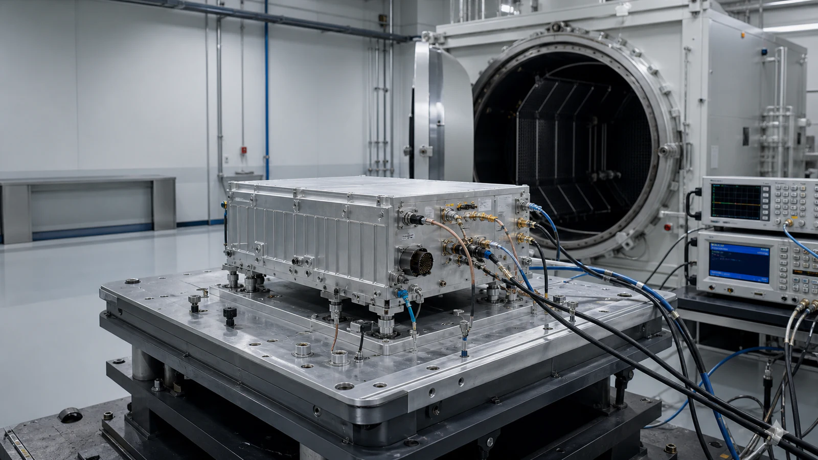
How should RF signal sources and timing hardware be selected?
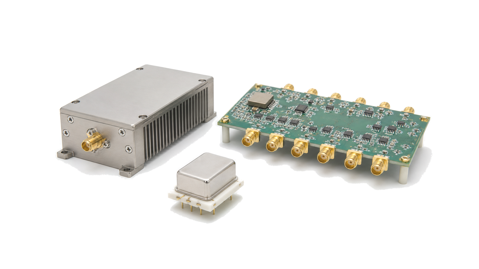
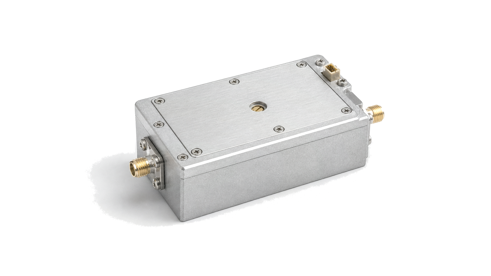
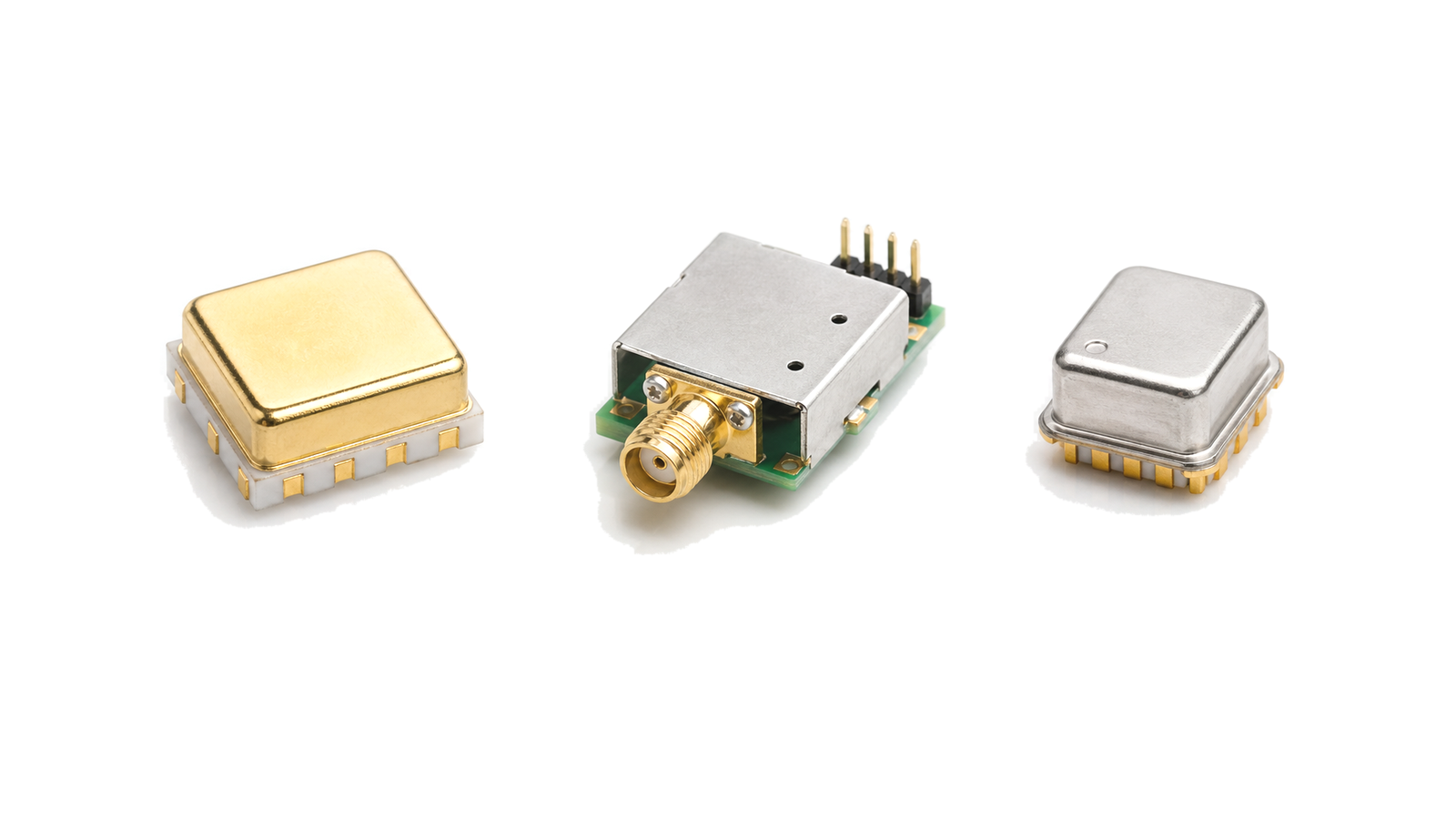
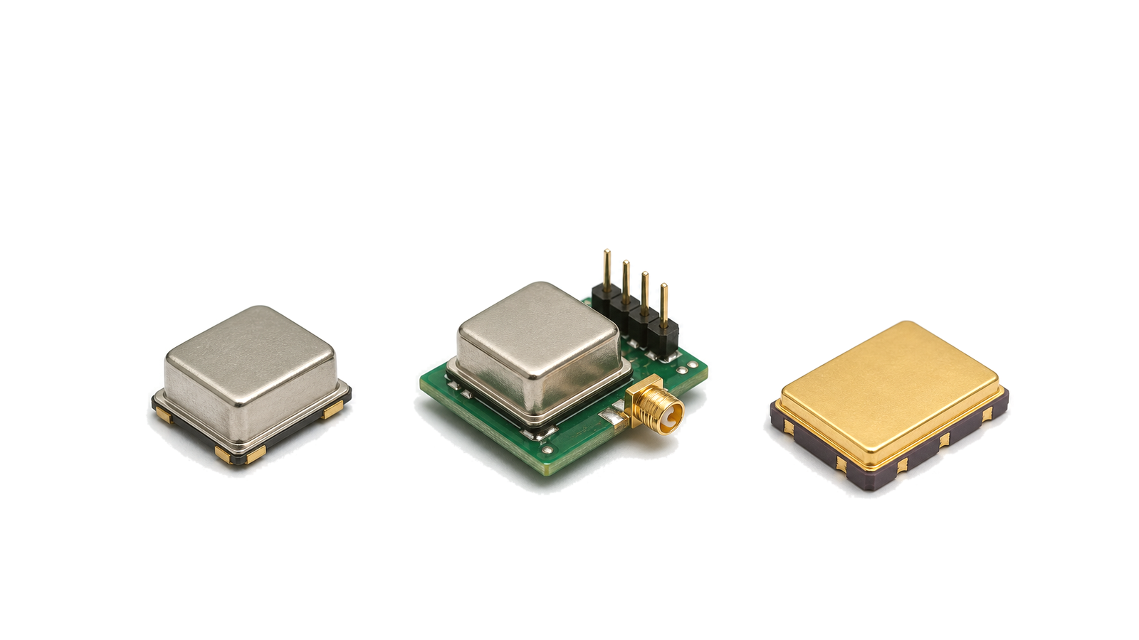
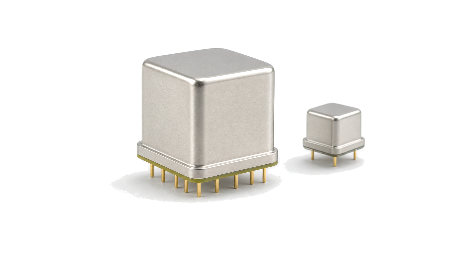
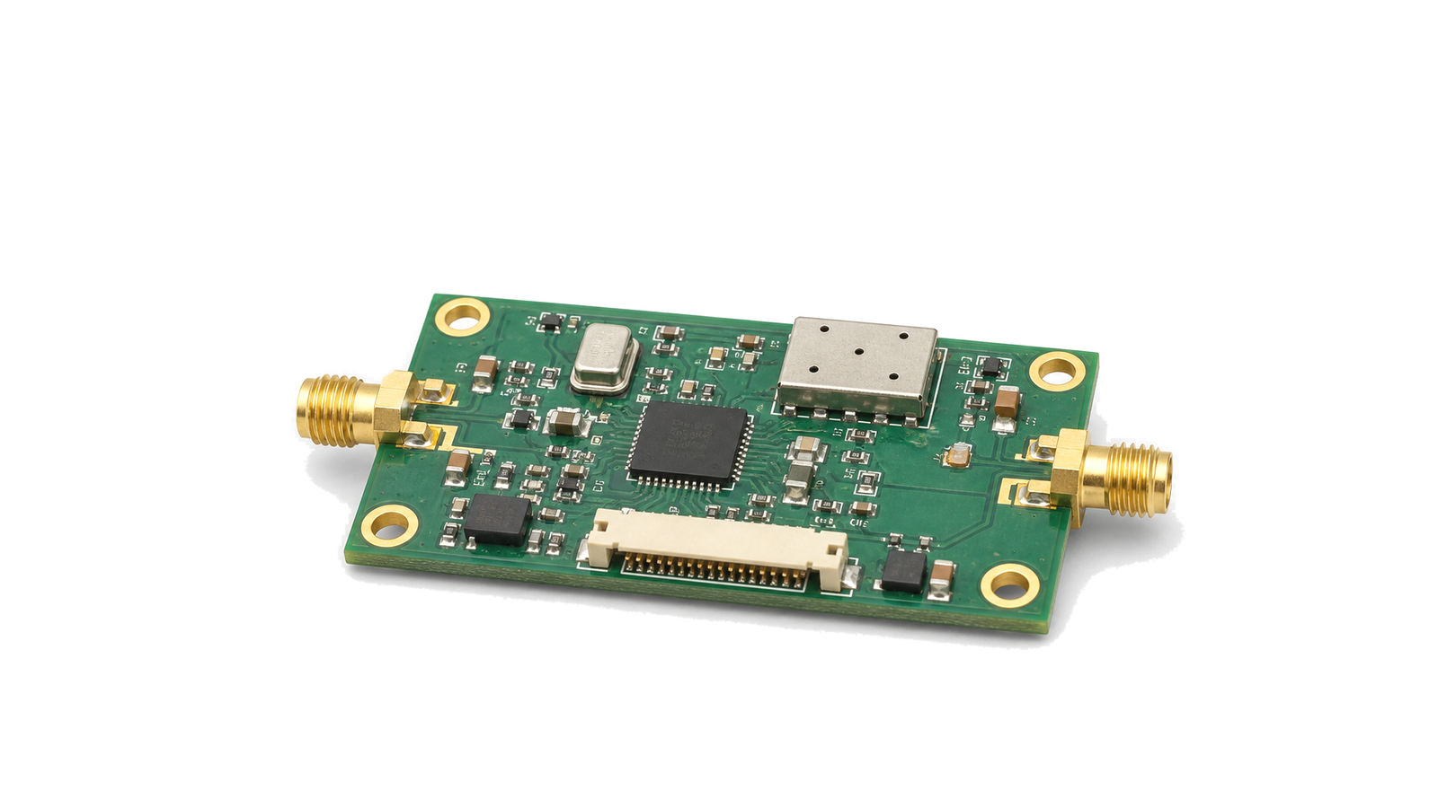
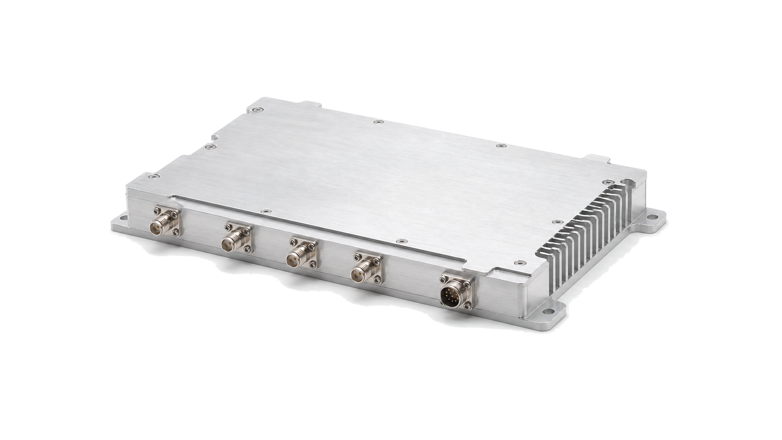
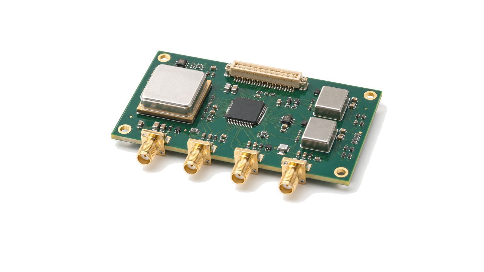
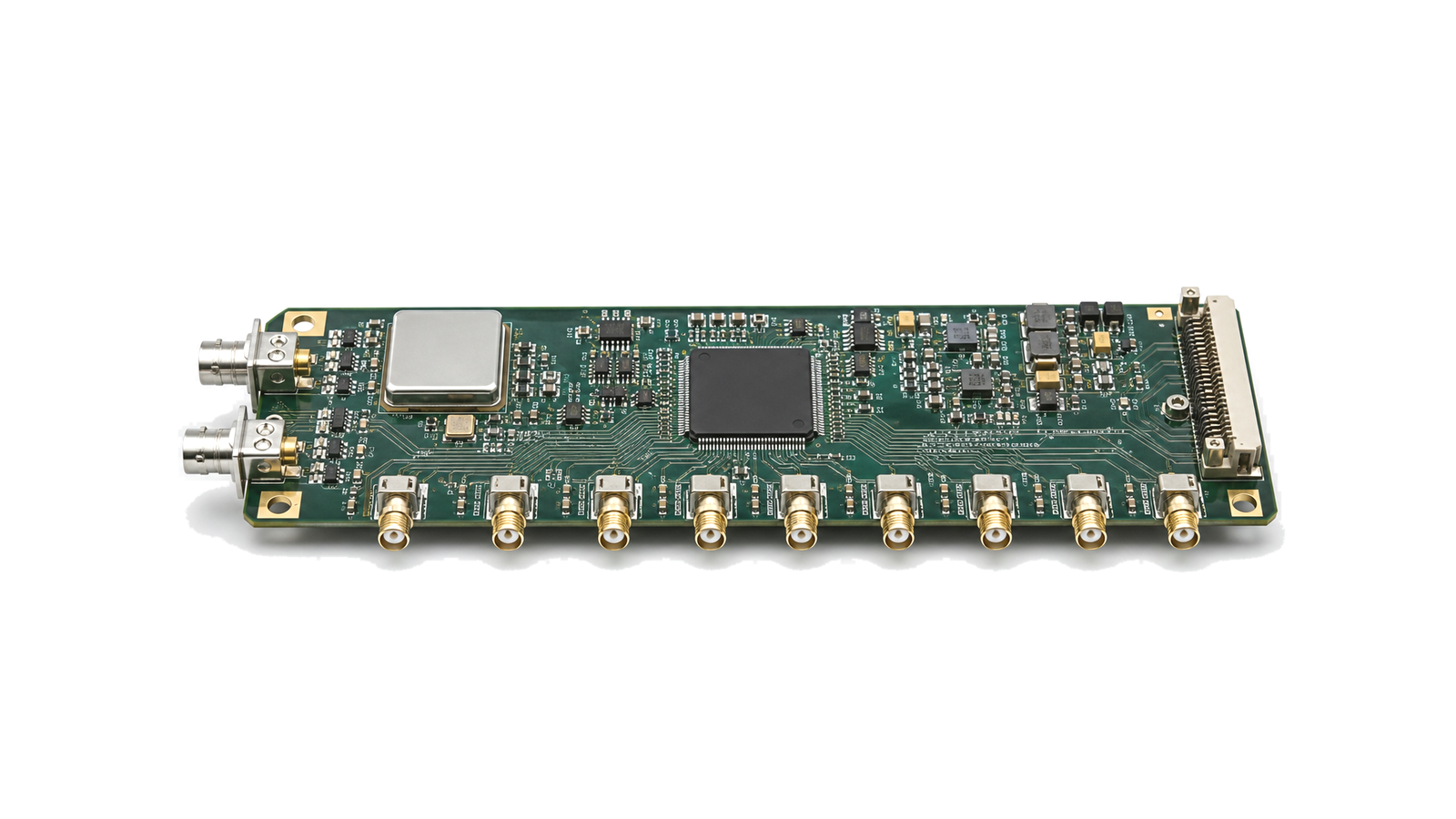
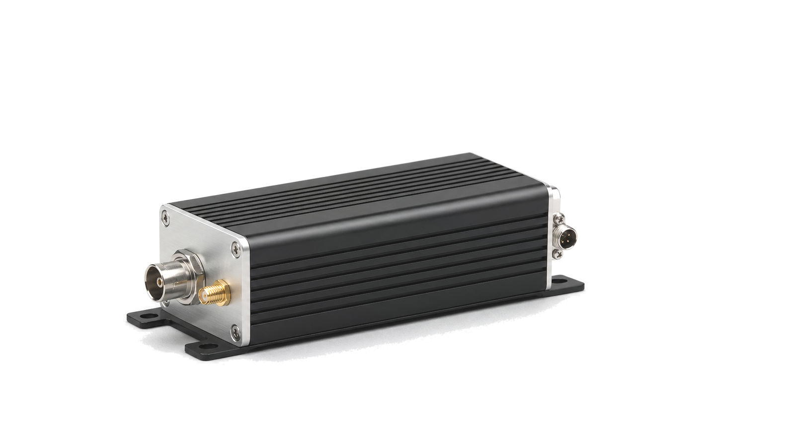
Specify an RF signal source at a named output reference plane and under a defined load, power, temperature and control state. Freeze the carrier ranges, step size, output level and waveform; allocate phase-noise limits over the offset regions that affect the system; bound harmonics, nonharmonic spurs and broadband noise; separate initial accuracy, temperature stability, aging and holdover; and define settling with a measurable error band and deadline. A shared reference or asserted lock signal is not proof of phase coherence or completed settling, so acceptance must retain traces from the actual tuning, restart and environmental states. A practical method for turning carrier, tuning, spectral-purity, reference-stability, switching and phase-coherence needs into an RF source specification that can be measured and accepted. Signal Sources & Timing covers RF and microwave hardware that establishes frequency, phase and timing references. It includes LO sources, crystal oscillators, PLLs, synthesizers, clock modules and reference distribution hardware.
Commercial and engineering decisions covered
- Signal Sources & Timing supplier: checks whether a supplier can support the required source architecture, interfaces, evidence and change control
- Signal Sources & Timing manufacturer: separates manufacturing repeatability and configuration control from a favorable prototype trace
- Signal Sources & Timing technical specifications: turns carrier, output, spectral purity, stability, switching and coherence into measurable limits
- Signal Sources & Timing selection guide: maps the system task to oscillator, VCO, PLL, synthesizer, reference or distribution families
- Signal Sources & Timing test and verification: verifies carrier, spectrum, timing and restart behavior at declared reference planes and states
Choose the family from the timing task
A fixed reference may use an XO, TCXO or OCXO according to warm-up, temperature, aging and holdover needs. An agile local oscillator normally adds a VCO, PLL or synthesizer whose tuning range, step, phase noise, spurs and settling are evaluated together. Clock modules and jitter cleaners serve distribution and data-converter timing, while reference and distribution modules coordinate several loads. The decision starts with whether the system needs accurate frequency, low short-term noise, rapid retuning, deterministic phase or continuity after reference loss.
Write one measurable source contract
Name every carrier range, forbidden band, step, sweep or hop, output level, flatness, impedance, waveform and load at a connector reference plane. Define phase noise as a mask over relevant offsets, and list harmonics, nonharmonic spurs, subharmonics and broadband noise separately. Initial accuracy, temperature variation, aging, warm-up, retrace and holdover are distinct budgets. Settling needs a start event, frequency and power transition, error band, observation bandwidth, dwell and deadline; a lock indication alone is not acceptance.
Evaluate supplier and manufacturing evidence
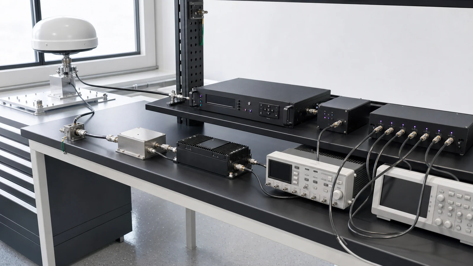
Compare guaranteed limits and test coverage rather than one typical plot. Ask which revision, reference, firmware, tuning mode, load, temperature, supply and measurement floor produced the data. Production evidence should identify calibration, fixtures, serial or lot traceability, acceptance records, oscillator or resonator source controls and notification rules for substitutions. For coherent or multi-output assemblies, cable delay, divider state, trigger distribution and calibration coefficients are part of the controlled configuration.
Verify frequency, spectrum and timing separately
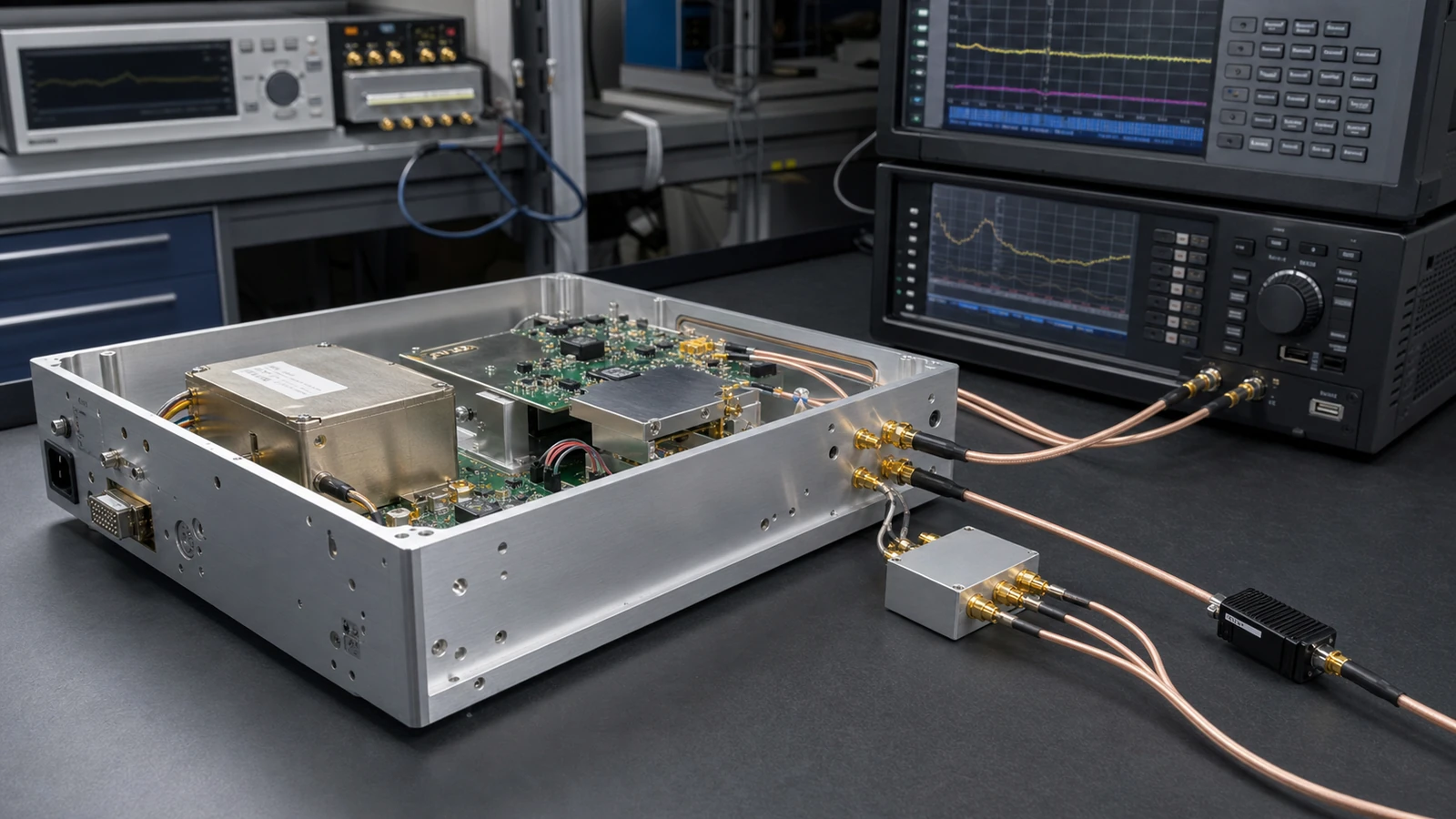
Measure output frequency and level at the named plane over operating states, then characterize phase noise with the instrument residual floor retained. Search deterministic products over a declared span and resolution bandwidth. Stability measurements preserve warm-up, environmental profile and observation interval. Capture switching from the real command or trigger until frequency, phase, level and spurs remain inside limits. Multi-channel coherence is repeated after retune, relock and power restart, because a shared reference proves common average frequency but not repeatable relative phase.
Signal-source and timing decision matrix
| System need | Likely family path | Evidence to compare |
|---|---|---|
| Stable frequency reference | TCXO, OCXO or reference module | Accuracy, warm-up, temperature, aging, retrace and holdover |
| Agile RF local oscillator | VCO, PLL or frequency synthesizer | Tuning coverage, phase-noise mask, spurs and settling |
| Low-jitter clock network | Clock module, jitter cleaner and distribution | Integrated band, additive jitter, skew, outputs and lock behavior |
| Coherent multi-channel source | Shared reference, trigger distribution and coherent synthesis | Relative phase, drift, retune, relock and restart repeatability |
| Traceable substitution source | Calibrated RF source or reference standard | Level and frequency uncertainty, spectral purity and calibration record |
RFQ inputs
- Use case, carrier ranges, forbidden bands, step size and tuning sequence
- Output power, accuracy, flatness, impedance, load, VSWR and reverse power
- Phase-noise mask by carrier and offset plus jitter integration band
- Harmonics, nonharmonic spurs, subharmonics, broadband noise and residual AM/FM
- Initial accuracy, warm-up, temperature, aging, vibration, retrace and holdover
- Reference input, loss-of-reference response, trigger and multi-output topology
- Switching start event, transition, error bands, observation bandwidth and deadline
- Supply, control, firmware, connector, enclosure and environmental conditions
- Measurement planes, residual floor, calibration, uncertainty and acceptance matrix
- Prototype and production quantities, traceability, data delivery and change notification
Evidence boundary
A family page identifies plausible source and timing architectures; it does not prove phase noise, spur, stability, settling or coherence for a particular unit. Approval requires configuration-specific guaranteed data and calibrated evidence at the agreed carrier, output, reference, load, temperature and control states.