
LCRF

Privacy preferences

Choose optional purposes independently. You can change or withdraw your choice at any time from the footer.

Strictly necessary

Required for security, session functions and storing your privacy choice.

Always active
Preferences

Remembers optional display or language settings when these features are enabled.

Analytics

Uses first-party visitor and session identifiers to measure pages, referrals and inquiry interactions.

Marketing

Allows marketing measurement or third-party advertising technologies if they are introduced in the future.

RF Power Amplifiers

RF power amplifiers raise RF or microwave signals to the output level required by a transmitter, test platform or dedicated RF subsystem. They are used in continuous-wave, pulsed, broadband and configured transmit-power paths.

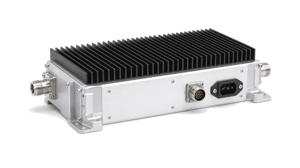
RF power amplifier module for transmit power stages

Articles

FAQ

How do continuous-wave and pulsed operation change power-amplifier requirements?

CW selection is governed by continuous dissipation and rated output; pulsed selection additionally requires peak power, pulse width, repetition rate, duty cycle, droop, recovery and protection.

What should be compared before selecting an RF amplifier family?

Choose the RF amplifier family from its signal-chain role first; then compare band, gain, noise or linearity, output, waveform, interfaces and thermal limits under equivalent conditions.

How should vehicle power transients, returns and chassis bonding be specified for RF hardware?

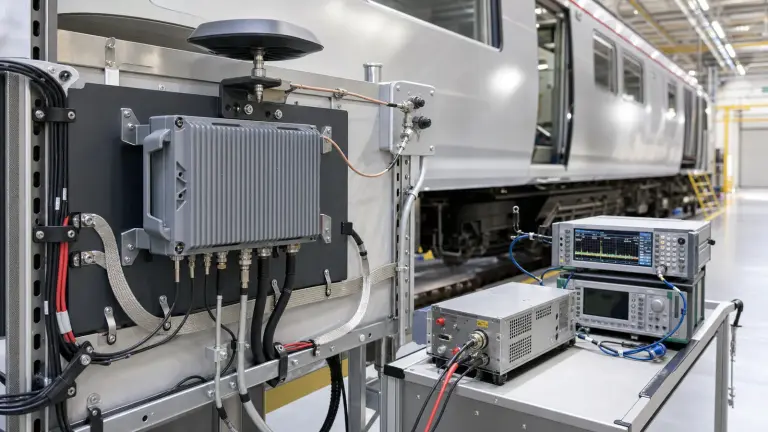
Specify the voltage and transient at the equipment terminals with source impedance and harness state, then control returns, shields and chassis bonds as separate verified paths.

What must be specified for a mobile-platform RF antenna and coax installation?

Define the installed antenna boundary, body or ground plane, feedthrough, protection, complete coax route, reference planes, mechanical support and replacement limits.

How are environmental and EMC tests tailored for rail, maritime, road and airborne RF hardware?

Derive test category, severity, axes, harness, operating modes and pass criteria from the exact installation rather than treating a platform standard as a universal certificate.

How should environmental requirements be written for aerospace RF hardware?

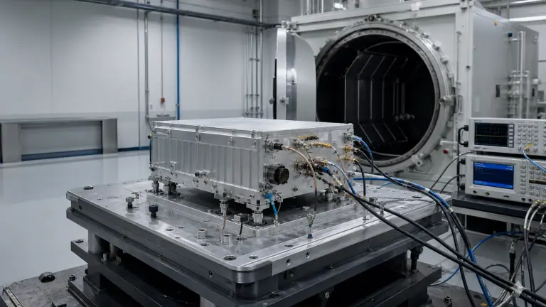
Derive stress, axes, duration, operating state, monitoring and pass criteria from the item boundary and actual storage, transport, launch or service profile instead of listing standards alone.

What qualification and acceptance evidence belongs with an RF payload or mission hardware delivery?

Deliver a requirement-linked verification matrix, article pedigree, approved procedures, raw results, uncertainty, environmental logs, anomalies and the exact configuration index for each unit.

What serviceability and lifecycle evidence should accompany mobile RF hardware?

Deliver installation identity, maintainability limits, acceptance results, diagnostics, spares and configuration-controlled change triggers that keep field evidence valid.

Which parts and configuration traceability records should accompany aerospace RF hardware?

Trace the delivered serial through BOM, approved sources, lots, processes, drawings, firmware, calibration, deviations and verification results so evidence can be tied to one configuration.

How should DMSMS, obsolescence and part substitutions be controlled in RF electronics?

Monitor supply risk across the life cycle, evaluate impact before shortages become urgent, and approve alternates through configuration control and requirement-based re-verification.

Engineering inquiry

Share your RF requirement

Share the product, operating requirements and project context. Our engineering team will route your request to the right specialist.

AttachmentsAttach drawings, BOMs, specifications or test files. Up to 5 files, 10 MB each and 25 MB total.
or drag and dropPDF, DOCX, XLSX, CSV, TXT, JPG, PNG, S1P and S2P
Typically reviewed within one business dayProject information is handled confidentially

RF power amplifiers

RF power amplifiers are output-stage modules that increase an RF or microwave drive signal to the power level required by the system. They appear in transmitters, RF stimulus systems, telemetry links, broadcast equipment, radar paths and purpose-built RF subsystems where the final delivered power must be controlled under known load and operating conditions.

Where they sit in the system

A power amplifier normally follows a driver stage and sits before filtering, coupling, antenna feed, load or test interface hardware. The useful boundary is the delivered RF output, not only small-signal gain. Operating band, rated output power, gain flatness, linearity, waveform duty, supply current, heat removal and mismatch behavior all affect how the amplifier behaves in the complete transmit path.