RF power amplifier test context
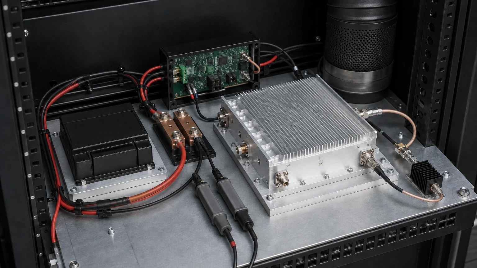
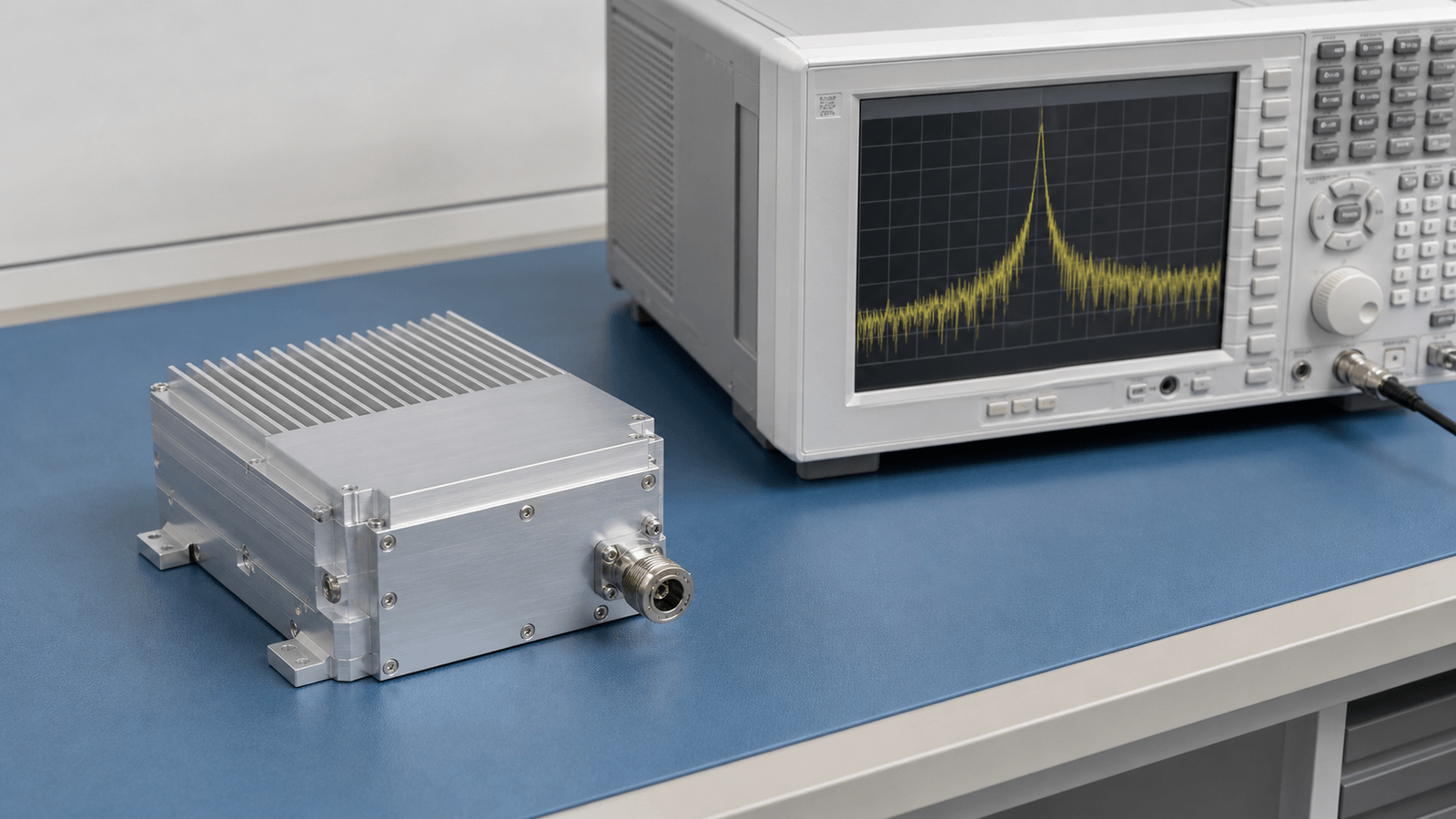
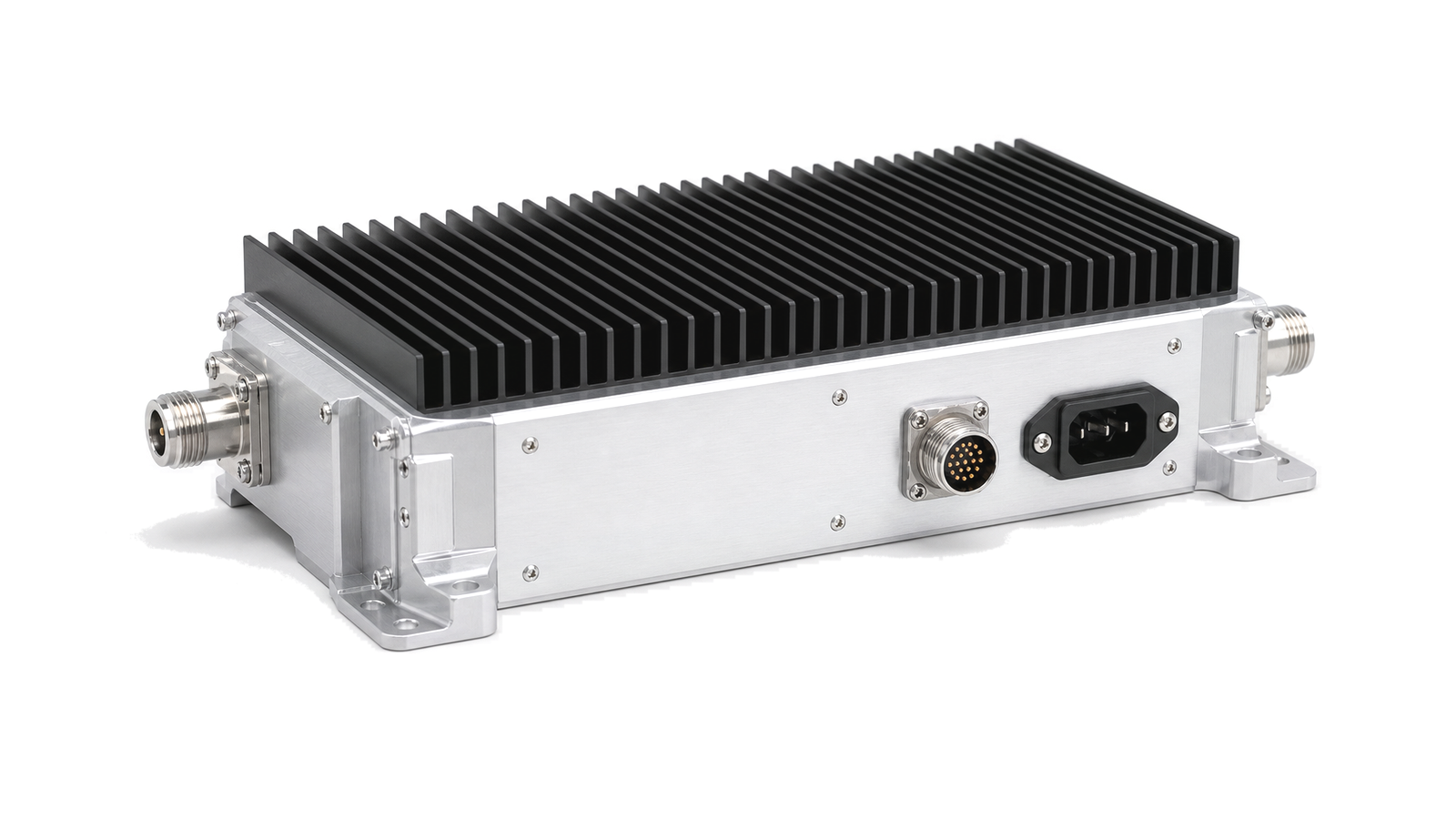
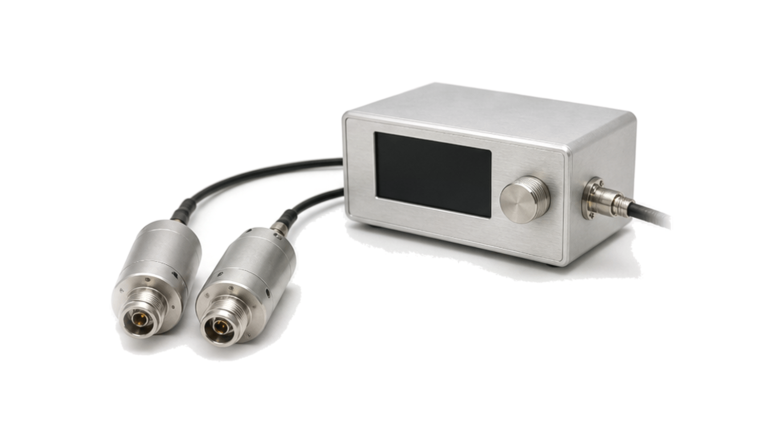
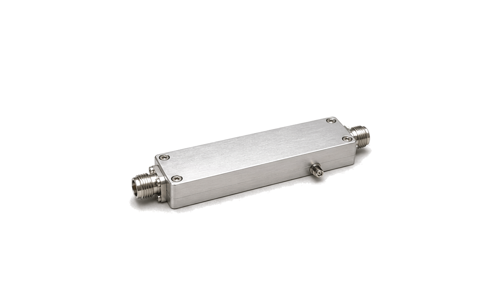
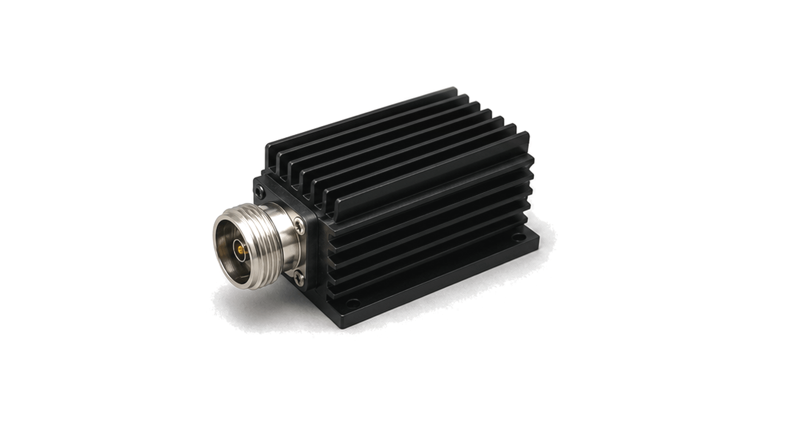
Power amplifier testing measures the delivered RF output of an amplifier under defined drive level, supply voltage, load impedance and temperature conditions. The test path usually combines a driver source, calibrated attenuation, directional coupling, a power sensor, an RF load and thermal observation so that electrical data is tied to the actual operating boundary.
What is usually recorded
Useful records include frequency band, saturated and linear output power, gain and gain flatness, harmonic and spurious levels, reflected-power response, shutdown behavior, supply current, control state and enclosure temperature. These results describe the amplifier as a power stage rather than a generic RF component.
Define one electrical-and-thermal operating envelope
- RF hardware for Power Amplifier Testing
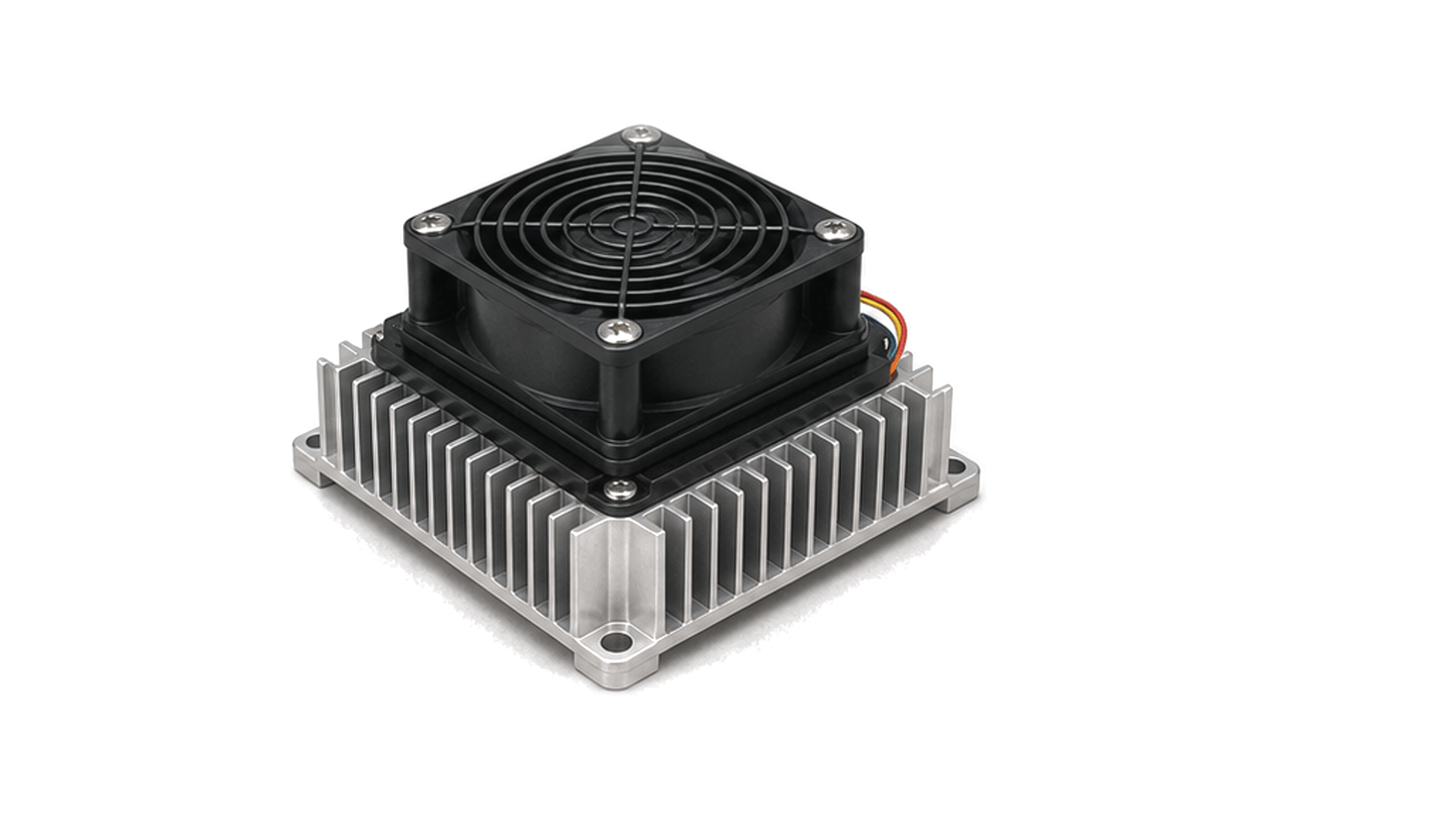
- Keep the article boundary on support hardware This workflow owns the DC source and conversion path, bias generation and sequencing, enable logic, protection and telemetry, module heat flow, cooling interface and the acceptance evidence that joins them....
- Power Amplifier Testing RF requirements
- Keep the article boundary on support hardware This workflow owns the DC source and conversion path, bias generation and sequencing, enable logic, protection and telemetry, module heat flow, cooling interface and the acceptance evidence that joins them....
- Power Amplifier Testing RF architecture
- Keep the article boundary on support hardware This workflow owns the DC source and conversion path, bias generation and sequencing, enable logic, protection and telemetry, module heat flow, cooling interface and the acceptance evidence that joins them....
- Power Amplifier Testing RF hardware selection
- Keep the article boundary on support hardware This workflow owns the DC source and conversion path, bias generation and sequencing, enable logic, protection and telemetry, module heat flow, cooling interface and the acceptance evidence that joins them....
- Power Amplifier Testing RF testing and verification
- Design one acceptance matrix that joins electrical, RF and thermal evidence Measure source and module-terminal voltage, rail current, enable and bias timing, fault response and declared temperatures while the RF module operates in the approved states....
How to Specify Power, Bias, Protection and Thermal Interfaces for an RF Power Module
An engineering workflow for turning RF operating modes into DC rail, current transient, ripple, sequencing, protection, heat-load, cooling-interface and acceptance requirements without confusing catalog ratings with delivered system performance.