
Low-loss RF cables
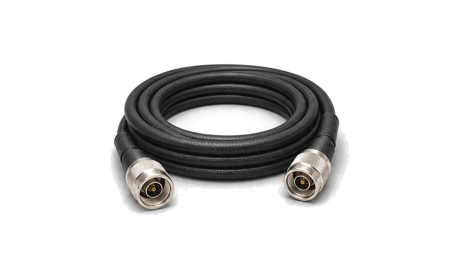
Low-loss RF cables are used when the interconnect path must preserve signal level over longer runs or loss-sensitive equipment layouts. They are selected for cable construction, dielectric behavior, shielding and connector termination rather than length alone.
Loss and routing data
Important data includes frequency range, attenuation per length, phase stability, return loss or VSWR, shielding effectiveness, power handling, minimum bend radius, jacket material, connector type and assembly length. These values help keep the cable contribution visible in the RF budget.
What does the Low-loss Cables category cover?
Low-loss RF cables carry microwave signals through longer or loss-sensitive routes where attenuation, phase stability and connector quality affect system margin.
How should hardware in the Low-loss Cables category be selected?
A field-ready method for specifying RF and microwave coaxial cable assemblies by topology, calibrated reference planes, insertion loss, return loss, power, phase and amplitude stability, delay, shielding, bend limits, connector control, environment and acceptance evidence.
- Freeze the finished two-port assembly before comparing cable series
- Start with topology, installation and service state
- Define continuous frequency coverage and both reference planes
Which specifications matter when evaluating Low-loss Cables?
Important data includes frequency range, attenuation per length, phase stability, return loss or VSWR, shielding effectiveness, power handling, minimum bend radius, jacket material, connector type and assembly length. These values help keep the cable contribution visible in the RF budget.
How should hardware in the Low-loss Cables category be tested and verified?
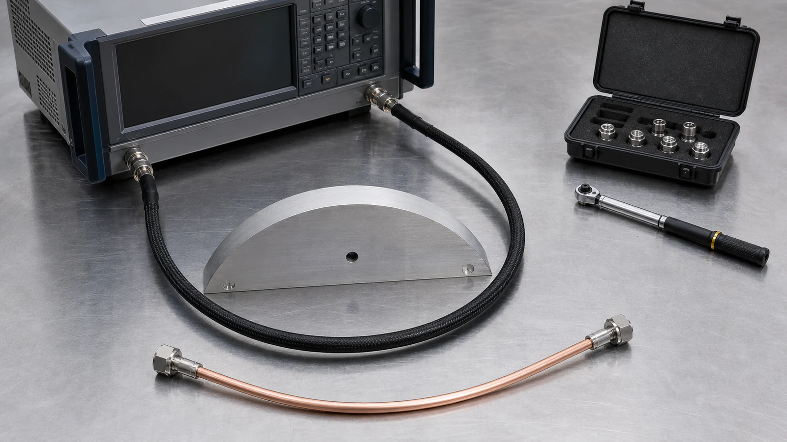
Specify an RF coaxial cable assembly as one controlled two-port configuration. Freeze both connector interfaces, gender and orientation, assembly length and tolerance, routing, minimum static and dynamic bend radius, continuous frequency band, reference impedance, insertion-loss and return-loss limits, average and peak power, phase or delay stability, shielding, temperature and environment. Define the calibrated reference planes, connector torque, preconditioning, flexure and thermal sequence, uncertainty, pass/fail limits and retained Touchstone or tabular data.