
LCRF

Privacy preferences

Choose optional purposes independently. You can change or withdraw your choice at any time from the footer.

Strictly necessary

Required for security, session functions and storing your privacy choice.

Always active
Preferences

Remembers optional display or language settings when these features are enabled.

Analytics

Uses first-party visitor and session identifiers to measure pages, referrals and inquiry interactions.

Marketing

Allows marketing measurement or third-party advertising technologies if they are introduced in the future.

Frequency Converters

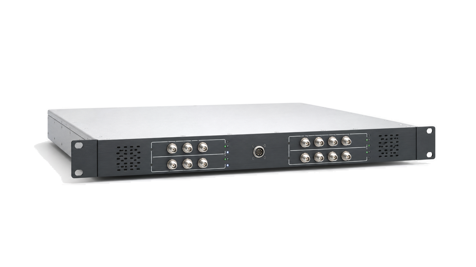
Antenna-facing hardware starts with radiation geometry. Frequency Converters sits within Frequency Conversion & IF Processing and groups related RF and microwave hardware with a shared function in the signal chain. The content focuses on frequency range, power level, gain or loss, impedance, connector format, package and environment for engineers, sourcing teams and system integrators.

Frequency Converters

Articles

FAQ

How should the simultaneous signal environment be specified for a spectrum-monitoring receiver?

Define weak signals and every simultaneous strong emitter by frequency, waveform, bandwidth, level, duty cycle, timing, antenna or conducted coupling plane and required observation outcome.

How should vehicle power transients, returns and chassis bonding be specified for RF hardware?

Specify the voltage and transient at the equipment terminals with source impedance and harness state, then control returns, shields and chassis bonds as separate verified paths.

How are environmental and EMC tests tailored for rail, maritime, road and airborne RF hardware?

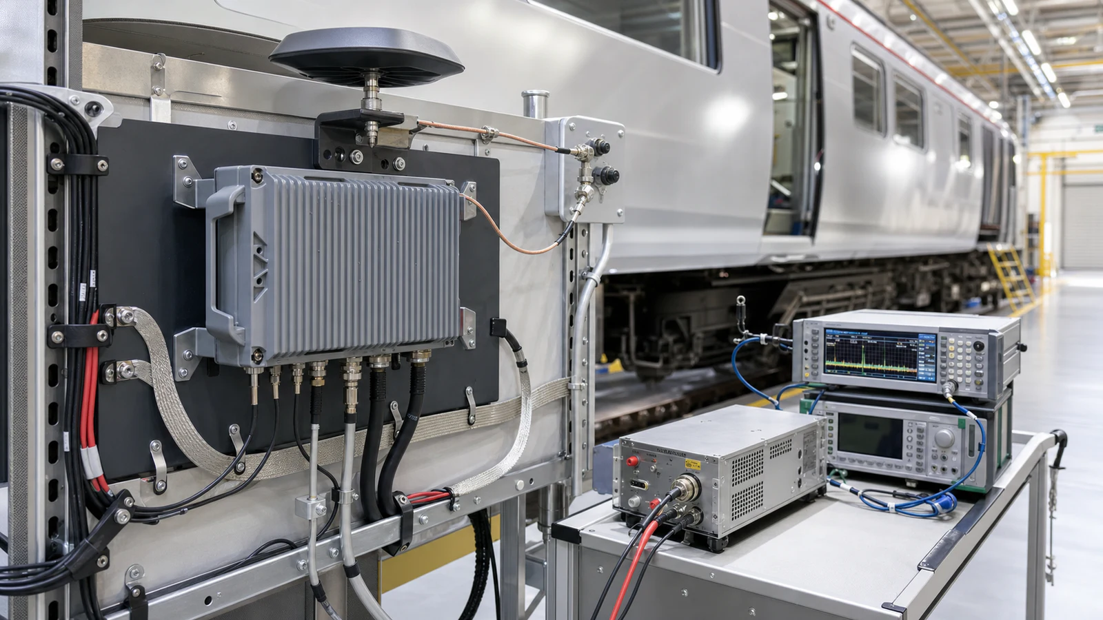
Derive test category, severity, axes, harness, operating modes and pass criteria from the exact installation rather than treating a platform standard as a universal certificate.

What must be specified for a mobile-platform RF antenna and coax installation?

Define the installed antenna boundary, body or ground plane, feedthrough, protection, complete coax route, reference planes, mechanical support and replacement limits.

How are RBW, dwell time and scan coverage related in spectrum monitoring?

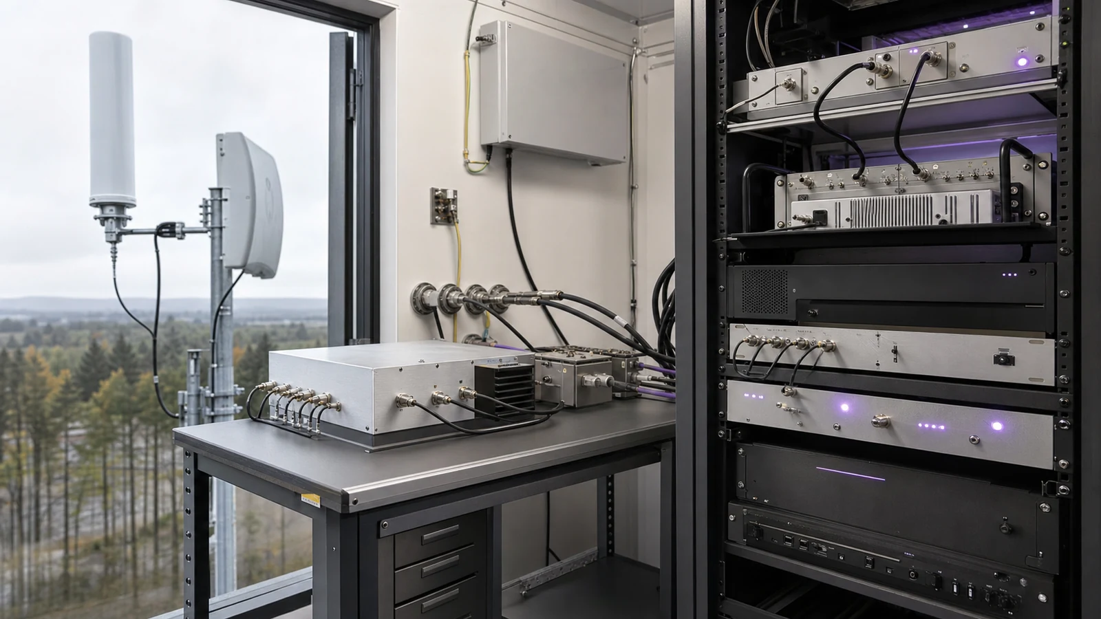
Coverage is bounded by monitored span, instantaneous bandwidth, step or FFT-bin spacing, RBW, settling and processing overhead, dwell per segment, revisit time and the duration of the event of interest.

How should preselection, blocker tolerance and overload limits be specified for a monitoring receiver?

Specify each band state by preselector rejection, insertion loss, gain or attenuation, noise figure, IP3 or compression, full-scale margin, overload indication and recovery under a simultaneous weak signal.

Which recording, timing and calibration interfaces belong in a spectrum-monitoring system specification?

Specify retained data, trigger and buffer behavior, complete RF metadata, time and frequency references, amplitude corrections, calibration injection, uncertainty and change-controlled export formats.

What serviceability and lifecycle evidence should accompany mobile RF hardware?

Deliver installation identity, maintainability limits, acceptance results, diagnostics, spares and configuration-controlled change triggers that keep field evidence valid.

Engineering inquiry

Share your RF requirement

Share the product, operating requirements and project context. Our engineering team will route your request to the right specialist.

AttachmentsAttach drawings, BOMs, specifications or test files. Up to 5 files, 10 MB each and 25 MB total.
or drag and dropPDF, DOCX, XLSX, CSV, TXT, JPG, PNG, S1P and S2P
Typically reviewed within one business dayProject information is handled confidentially

Frequency Converters

Antenna-facing hardware starts with radiation geometry. Frequency Converters groups related RF and microwave hardware with a shared function in the signal chain for communication equipment, radar systems, satellite links, RF test platforms and industrial hardware. The information is organized around how this hardware is used in an RF system.

Key data centers on frequency range, power level, gain or loss, impedance, connector format, package and environment. Those details help engineering, sourcing and integration teams compare the record against the actual signal path, mechanical boundary and operating environment.

When reviewed with model data, outline dimensions, test conditions and delivery documents, the content makes project scope, constraints and follow-up verification points easier to align early.