
LCRF

Privacy preferences

Choose optional purposes independently. You can change or withdraw your choice at any time from the footer.

Strictly necessary

Required for security, session functions and storing your privacy choice.

Always active
Preferences

Remembers optional display or language settings when these features are enabled.

Analytics

Uses first-party visitor and session identifiers to measure pages, referrals and inquiry interactions.

Marketing

Allows marketing measurement or third-party advertising technologies if they are introduced in the future.

RF Attenuation, Detection & Power Monitoring

Design RF attenuation, detection and monitoring paths by level-control task, waveform, dynamic range, response time, directional sampling, power, calibration and protection limits.

Attenuation, Detection & Monitoring

Categories

Articles

FAQ

How should preselection, blocker tolerance and overload limits be specified for a monitoring receiver?

Specify each band state by preselector rejection, insertion loss, gain or attenuation, noise figure, IP3 or compression, full-scale margin, overload indication and recovery under a simultaneous weak signal.

Which recording, timing and calibration interfaces belong in a spectrum-monitoring system specification?

Specify retained data, trigger and buffer behavior, complete RF metadata, time and frequency references, amplitude corrections, calibration injection, uncertainty and change-controlled export formats.

How are RBW, dwell time and scan coverage related in spectrum monitoring?

Coverage is bounded by monitored span, instantaneous bandwidth, step or FFT-bin spacing, RBW, settling and processing overhead, dwell per segment, revisit time and the duration of the event of interest.

How should the simultaneous signal environment be specified for a spectrum-monitoring receiver?

Define weak signals and every simultaneous strong emitter by frequency, waveform, bandwidth, level, duty cycle, timing, antenna or conducted coupling plane and required observation outcome.

How do coupling factor, directivity and return loss affect forward and reflected-power accuracy?

Coupling factor sets the sampled level, directivity limits separation of forward and reverse waves, and return loss determines how strongly the coupler and its interfaces disturb or re-reflect the signal. Detector accuracy alone cannot define the accuracy of a forward/reflected-power measurement.

What must a radar Tx/Rx protection requirement include beyond receiver survival?

A complete Tx/Rx protection requirement includes survivable peak and average leakage, limiter and switch behavior, residual level, overload recovery, post-pulse gain/noise/phase and the nearest usable range gate.

How often should an RF test path be verified with a check standard or recalibrated?

Use both time-based intervals and event triggers, with an independent check standard that can reveal drift, cable or connector damage, switch-state change and fixture instability between full calibrations.

How are RF termination return loss, VSWR, reflection coefficient and mismatch loss related?

Return loss and VSWR express the reflection coefficient at one reference plane; reflected power and mismatch loss follow from its magnitude.

How should RF P1dB and two-tone intermodulation tests differ?

P1dB is a single-tone gain-compression sweep, while two-tone IMD measures nonlinear mixing products with stated tone spacing, per-tone power and system residual checks; the results answer different questions.

Why must a passive RF impedance network have a defined reference plane and complex S-parameters?

The reference plane determines where impedance and waves are defined; complex S-parameters retain magnitude and phase needed to move planes, de-embed fixtures and predict network interaction.

What is an RF measurement reference plane, and when is fixture de-embedding required?

The measurement reference plane is the electrical boundary where a corrected value is claimed; de-embedding is needed only when a characterized fixture network must be removed to report at a different DUT plane.

Engineering inquiry

Share your RF requirement

Share the product, operating requirements and project context. Our engineering team will route your request to the right specialist.

AttachmentsAttach drawings, BOMs, specifications or test files. Up to 5 files, 10 MB each and 25 MB total.
or drag and dropPDF, DOCX, XLSX, CSV, TXT, JPG, PNG, S1P and S2P
Typically reviewed within one business dayProject information is handled confidentially

How should attenuation, detection and monitoring be divided in an RF chain?

Use attenuation to set or protect RF level, detection to convert a sampled RF waveform into a measurable video or DC quantity, and monitoring to combine directional sampling, calibrated detection, logic and limits into an operational measurement. These functions are related but their accuracy, bandwidth and protection claims are not interchangeable.

Choose the function before the component family

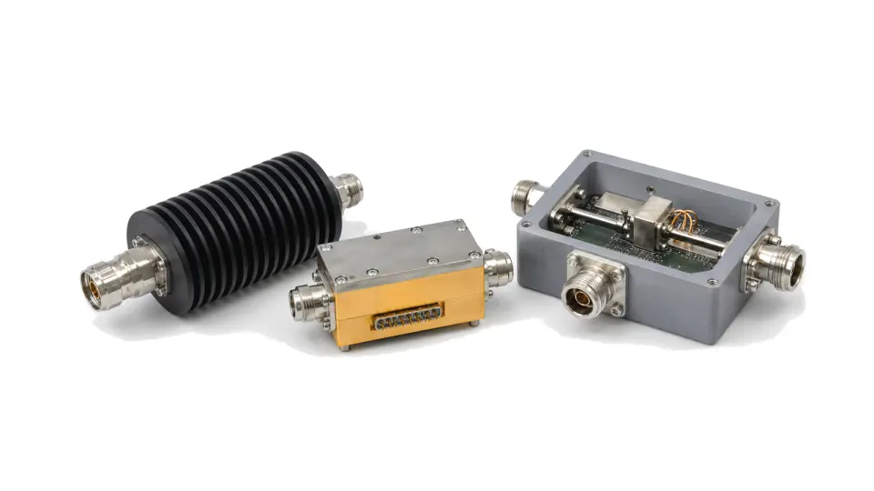
A fixed attenuator establishes a known loss or improves match; a variable or digital step attenuator closes gain-control and calibration loops; a limiter protects a downstream input; a detector reports envelope, logarithmic level or true-RMS power; and a monitor adds couplers, calibration, thresholds and control. Define whether the result drives AGC, ALC, interlock, telemetry, VSWR protection or a traceable test result before selecting hardware.

Specify attenuation in every operating state

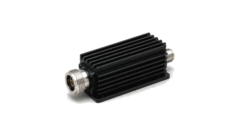
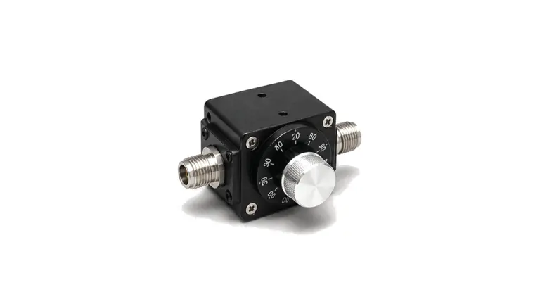
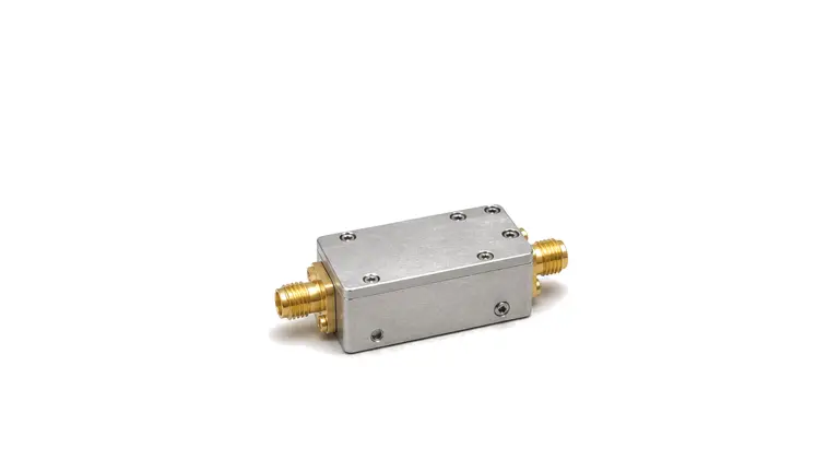
State frequency, nominal loss, range, step size or control law, attenuation accuracy and flatness. Include insertion loss in the reference state, return loss, relative phase, amplitude and phase settling, monotonicity, control interface and state-transition glitch. Power handling must cover average and peak input, crest factor, hot switching and the worst source or load mismatch. For a receive path, include the attenuator loss in noise-figure and sensitivity budgets.

Match detector law to waveform and time response

Envelope and diode detectors suit carrier presence and fast peak behavior; logarithmic detectors offer wide level range and useful dB-linear outputs; RMS detectors better represent waveforms whose crest factor or modulation changes. Specify RF input band separately from video bandwidth, rise and fall time, minimum pulse width and output filtering. Add usable dynamic range, sensitivity, slope, intercept, law-conformance error, output noise and drift over frequency, temperature and supply.

Treat forward and reflected power as a directional measurement

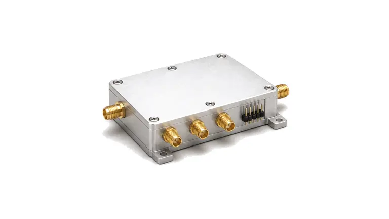
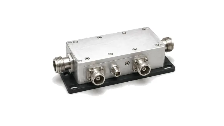
A VSWR or reflected-power monitor needs a directional coupler or bridge with known coupling, directivity and insertion loss, followed by matched detection channels. Poor directivity, unequal detector laws and cable phase create false reflected power. Define the power threshold below which a ratio or VSWR is invalid, the reference plane, calibration factors and shutdown delay. Calibrate the complete sampling path rather than assuming detector voltage equals delivered power.

Close calibration from RF port to reported value

Document coupler orientation, attenuator state, detector termination, video load, ADC range, linearization table, temperature compensation and units. Establish reference planes for source, load and monitored port. Use known-power sweeps across frequency, attenuation state, waveform and temperature; repeat anchor points after reconnection. Report saturation, under-range and invalid-ratio states explicitly instead of clipping them into plausible readings.

Define acceptance around the control loop

Verify small-signal transfer, high-power compression, recovery from overload, state switching, pulse response and alarm timing with representative mismatch. Confirm that attenuation commands, measured level and protection thresholds remain coherent after warm-up and supply variation. Acceptance files should preserve raw detector voltage or counts, applied RF power, calibration version, limits and event timestamps so field behavior can be traced.

RFQ inputs for attenuation and monitoring hardware

  • Frequency band and impedance
  • Fixed loss or variable attenuation range
  • Step, control law, accuracy, flatness and phase
  • Waveform, crest factor, pulse width and duty cycle
  • Dynamic range, response time and video bandwidth
  • Average, peak and hot-switch power
  • Forward and reflected sampling architecture
  • Coupler directivity and calibration plane
  • Temperature, supply and output interface
  • Alarm, interlock, recovery and acceptance records

Category boundary

This category covers RF attenuators, detectors, log-video amplifiers, power-detection modules, limiters and forward/reflected-power monitors used to control, sense or protect signal level. It excludes general-purpose test instruments, complete receivers, power amplifiers, standalone directional couplers and digital control systems unless they are integral to the delivered monitoring function.