
LCRF

Privacy preferences

Choose optional purposes independently. You can change or withdraw your choice at any time from the footer.

Strictly necessary

Required for security, session functions and storing your privacy choice.

Always active
Preferences

Remembers optional display or language settings when these features are enabled.

Analytics

Uses first-party visitor and session identifiers to measure pages, referrals and inquiry interactions.

Marketing

Allows marketing measurement or third-party advertising technologies if they are introduced in the future.

RF Switches

RF switches control signal paths inside receiver, transmitter, test and protection circuits. They are used when a system needs defined routing between RF ports with known frequency range, insertion loss, isolation, control logic and power handling.

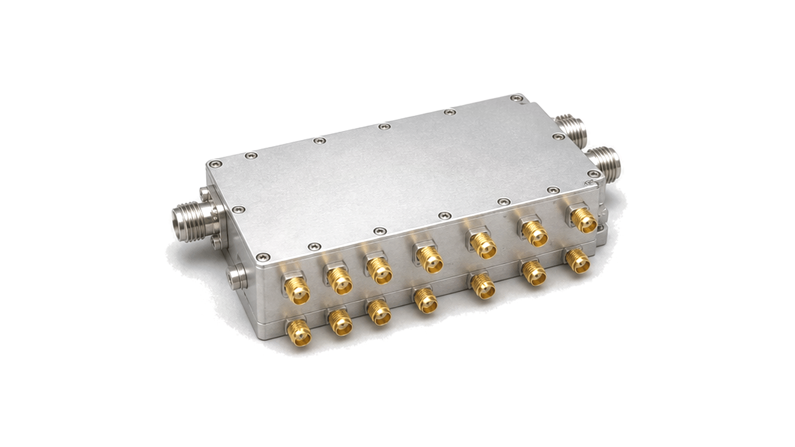
RF switch module for signal path control

Articles

FAQ

How should preselection, blocker tolerance and overload limits be specified for a monitoring receiver?

Specify each band state by preselector rejection, insertion loss, gain or attenuation, noise figure, IP3 or compression, full-scale margin, overload indication and recovery under a simultaneous weak signal.

How should the simultaneous signal environment be specified for a spectrum-monitoring receiver?

Define weak signals and every simultaneous strong emitter by frequency, waveform, bandwidth, level, duty cycle, timing, antenna or conducted coupling plane and required observation outcome.

Which recording, timing and calibration interfaces belong in a spectrum-monitoring system specification?

Specify retained data, trigger and buffer behavior, complete RF metadata, time and frequency references, amplitude corrections, calibration injection, uncertainty and change-controlled export formats.

How are RBW, dwell time and scan coverage related in spectrum monitoring?

Coverage is bounded by monitored span, instantaneous bandwidth, step or FFT-bin spacing, RBW, settling and processing overhead, dwell per segment, revisit time and the duration of the event of interest.

Engineering inquiry

Share your RF requirement

Share the product, operating requirements and project context. Our engineering team will route your request to the right specialist.

AttachmentsAttach drawings, BOMs, specifications or test files. Up to 5 files, 10 MB each and 25 MB total.
or drag and dropPDF, DOCX, XLSX, CSV, TXT, JPG, PNG, S1P and S2P
Typically reviewed within one business dayProject information is handled confidentially

RF Switches

RF switches route signals between defined paths inside an RF or microwave circuit. They may be implemented as compact modules or board-level assemblies when the design needs electronic path control rather than manual cable changes.

System role

They appear in receiver front ends, transmit chain routing, protection circuits, automated test fixtures and multi-channel modules that need repeatable port-to-port behavior.

Key data

Important records include switch topology, frequency range, insertion loss, isolation, return loss, switching speed, control logic, RF power limit, bias requirements and operating temperature.