Control the complete path, not a list of nominally compatible parts
A defensible waveguide decision joins mode control, aperture and flange geometry, alignment, electrical budget, power environment, calibrated reference planes and retained evidence for the same physical assembly. At millimeter-wave frequencies, small aperture displacement, flange-face damage, unsupported weight, converter movement or a changed calibration plane can be large compared with the wavelength. The specification must therefore name dimensions, interfaces, test planes and conditions rather than relying on family names alone.
Freeze band, mode and every discontinuity before selecting hardware
Start with the continuous operating band, verification band and any guard band rather than a center frequency. Name the waveguide designation and internal aperture, intended dominant mode, polarization and propagation direction. Check cutoff margin and the risk of higher-order modes for the actual aperture, transitions and bends. Frequency overlap on two catalog pages does not establish low-loss compatibility or mode purity.
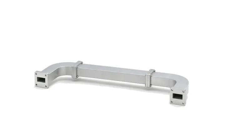
Draw the entire path from the calibrated source plane to the calibrated receive or load plane. Include straight sections, bends, twists, tapers, steps, coax launches, windows, flexible sections, orthomode functions, couplers, isolators, loads and removable adapters. Identify where polarization rotates, cross-section changes or symmetry is broken. Those locations own reflection, conversion, field concentration and mechanical tolerance risk.
Specify flange geometry, surface condition and assembly repeatability
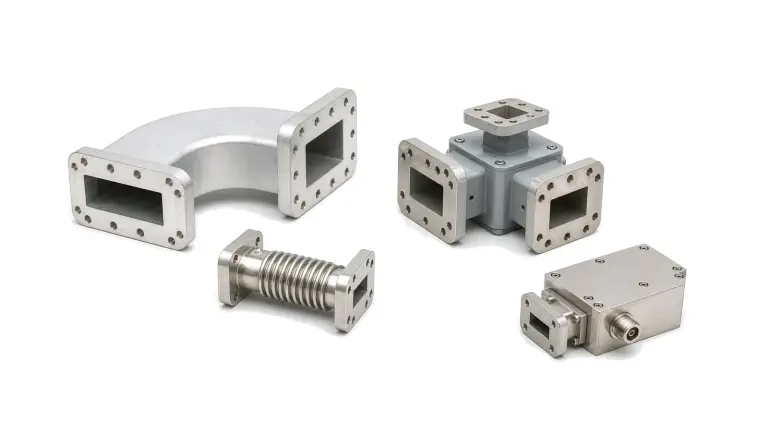
For every joint, state the flange family and drawing, aperture dimensions and orientation, cover or choke form, mating face, alignment pins, fastener pattern, gasket or seal and clocking datum. Do not treat visually similar flanges as interchangeable. A compatible bolt pattern can still conceal a shifted aperture, wrong orientation, different locating scheme or a reference plane that moves when an adapter is added.
Control face flatness, perpendicularity, aperture position, burrs, plating, surface damage and cleanliness. Define support points, allowed cantilever load, fastener sequence, torque method and remate limit. Inspect before assembly and after environmental or high-power work. Connection repeatability should be measured through deliberate disconnect and reconnect cycles with cables, converters and heavy components mechanically supported.
Allocate loss, match, isolation and phase to named reference planes
Build an electrical budget across frequency and temperature for insertion loss, return loss or VSWR, isolation, directivity, amplitude balance, phase, group delay and leakage as applicable. Assign each limit to a defined two-port or multiport boundary. Separate component limits from adapter, flange-pair and complete-path limits so a failed assembly can be diagnosed rather than hidden inside one aggregate number.
Account for conductor loss, surface roughness and finish, path length, bends, twists, tapers, junction mismatch, leakage and temperature-driven dimensional change. For couplers, circulators and orthomode devices, include all terminated and driven port states. For phase-sensitive arrays or coherent chains, control electrical length and remate repeatability, not only room-temperature insertion loss.
Treat peak power, average heating and pressure state as different limits
Define waveform, peak and average power, pulse width, duty, repetition rate, mismatch, fault duration and which port can be energized. Peak electric field can drive breakdown while average dissipation controls temperature; neither is inferred safely from the other. Include transition steps, flange gaps, sharp edges, windows, contaminants and pressure changes because local field concentration can dominate a long straight section.
State ambient or base temperature, gas or purge, pressure, altitude or vacuum, cooling and heat-removal path. Where multipactor, corona or arcing matters, require configuration-specific analysis and test evidence for geometry, material, finish, field and power rather than a universal family rating. Define interlocks, ramping, reflected-power limits, inspection and post-test RF checks before power is applied.
Make calibration standards, reference planes and uncertainty part of the design
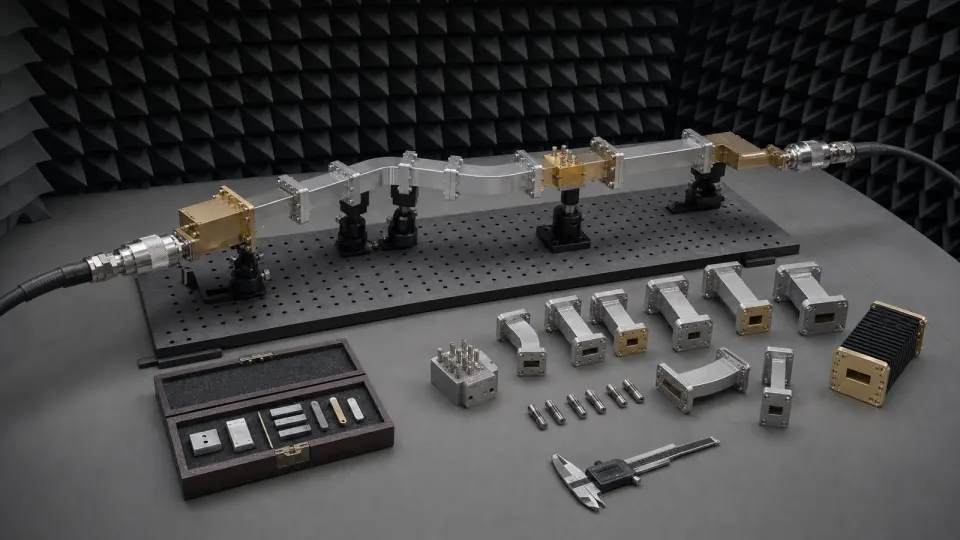
Choose a VNA calibration method and standard set that match the waveguide band, port topology and insertability. Record standard definitions, dimensions, line or offset values, kit identity, temperature and certificate status. State where the calibrated planes are located and whether adapters, tapers, converters, fixtures or support movement remain in the result. A successful instrument calibration indicator does not prove that the physical reference plane matches the drawing.
Use verification standards and residual checks that are independent enough to reveal a poor calibration. Quantify connection repeatability, drift, cable or converter movement, leakage, receiver dynamic range and dimensional uncertainty. Non-insertable or directional devices may require two calibrations or an adapter-characterization method; preserve native complex data and the uncertainty propagation rather than reporting corrected plots alone.
Close acceptance with dimensional, RF and configuration evidence
The acceptance package should identify every part and serial, material and finish, controlled drawing revision, flange and aperture inspection, assembly orientation, support configuration, calibration and instrument state, environmental condition, raw complex data, corrected result, uncertainty and pass limits. Photographs can support configuration identity, but they do not replace dimensions or RF evidence. Record any adapter used during acceptance and whether it ships with the assembly.
Define incoming inspection, assembly traveler, cleaning and protective-cap rules, storage, remate controls, repair and re-test triggers. Changes to flange source, internal dimensions, plating, machining method, material, braze, length, support or calibration standard can alter the result even when the family name is unchanged. Approve substitutions only after interface, electrical, power, metrology and documentation impacts are reviewed.
| Decision boundary | Evidence to freeze | Reject the proposal when |
|---|---|---|
| Band and mode | Operating and verification bands, aperture, designation, dominant mode, polarization and cutoff margin | Only center frequency or a catalog band name is stated |
| Path topology | All bends, twists, tapers, launches, windows, adapters, passives and terminated ports | The quoted component is detached from the assembled path |
| Flange interface | Drawing, aperture position, clocking, locating scheme, face form, fasteners, seal and mating part | Matching bolt holes are treated as full compatibility |
| Electrical budget | Reference planes, loss, match, isolation, directivity, phase, delay, leakage, temperature and margin | Limits have no frequency, plane or condition |
| Power boundary | Waveform, peak, average, duty, mismatch, fault, pressure, material, finish, temperature and cooling | One nominal power number is used for every environment |
| Mechanical build | Length, electrical length, bend and twist geometry, flatness, support, load, torque, cleanliness and remates | Heavy hardware hangs from the measurement or DUT flange |
| Calibration | Method, standards, definitions, kit identity, planes, insertability, residual check, repeatability and uncertainty | A corrected trace is supplied without a reviewable calibration chain |
| Acceptance | Serial identity, drawings, inspection, configuration, raw data, uncertainty, limits, changes and re-test triggers | A generic certificate replaces exact-assembly evidence |
Worked decision: a 39.5 GHz path that fits mechanically can still fail metrology
A receive path uses two coax-to-waveguide launches, a twist, a directional device and a removable test adapter around 39.5 GHz. The parts overlap in frequency and the bolt patterns appear to mate, but one joint uses a different locating scheme and the directional device is non-insertable in the ordinary through-connection. The controlled review freezes the aperture and flange drawings, polarization, clocking, support points and reference planes; allocates loss, return loss, directivity and phase by subassembly; and defines a band-appropriate two-stage calibration with an adapter characterization and repeatability cycles. Acceptance retains native complex data, residual checks and uncertainty. The decision changes from 'the parts fit' to 'the assembled, supported and calibrated path meets the electrical budget at named planes.'

Build the waveguide specification and verification flow
- Approve operating, guard and verification bands, aperture, designation, intended mode, polarization and propagation direction.
- Release a path drawing that includes every transition, bend, twist, window, adapter, passive, termination and removable test item.
- Freeze flange drawings, aperture position, clocking, alignment scheme, face form, fasteners, seals and mating parts.
- Allocate loss, return loss, isolation, directivity, phase, group delay and leakage to named reference planes and conditions.
- Approve material, finish, roughness, internal geometry, length, flatness, support, load, cleaning and assembly controls.
- Define waveform, peak and average power, mismatch, fault duration, temperature, pressure or vacuum, cooling and safety interlocks.
- Select calibration method and standards for band, topology and insertability; retain definitions, identities and dimensional evidence.
- Measure residuals, disconnect/reconnect repeatability, drift, movement sensitivity, leakage and uncertainty before DUT acceptance.
- Verify RF, phase and power behavior on the exact supported assembly across the required frequency and environmental states.
- Release serial-linked drawings, inspection, calibration, native data, corrected results, uncertainty, pass limits and change triggers.
Common waveguide decisions that should be rejected
- Selecting by center frequency without checking aperture, cutoff margin and higher-mode risk.
- Assuming equal bolt patterns prove flange, aperture, polarization and reference-plane compatibility.
- Ignoring bends, twists, tapers, adapters or support loads in the quoted electrical budget.
- Specifying insertion loss without a reference plane, temperature, flange-pair count or uncertainty.
- Using one power number without waveform, duty, mismatch, pressure, finish or thermal boundary.
- Allowing heavy converters or test heads to cantilever from a precision flange.
- Cleaning damaged faces without dimensional inspection or defined repair limits.
- Calibrating through an adapter and then removing it without an adapter-removal method.
- Accepting corrected plots while raw data, standard definitions and residual checks are unavailable.
- Approving a material, plating, machining or flange-source change because the part name did not change.
Information to include in a waveguide or millimeter-wave RFQ
- Operating, guard and verification frequency bands
- Waveguide designation, internal aperture, intended mode and polarization
- Complete path topology and port map, including removable adapters and terminations
- Flange drawings, mating parts, clocking, alignment, fasteners, seals and orientation
- Insertion loss, return loss, isolation, directivity, phase, delay and leakage limits with planes and conditions
- Waveform, peak and average power, pulse width, duty, repetition rate, mismatch and fault duration
- Temperature, pressure, altitude or vacuum, gas, cooling and environmental states
- Material, plating, finish, roughness, cleanliness and internal geometry controls
- Mechanical length, electrical length, bend and twist geometry, flatness, tolerance and support loads
- Assembly, torque, cleaning, inspection, protection and remate requirements
- Calibration method, kit and standard definitions, reference planes and insertability constraints
- Required uncertainty, repeatability, residual, drift and native-data evidence
- Power, environmental, dimensional and RF acceptance methods and pass limits
- Serial traceability, drawing revision, certificates, change notification, substitutions and re-test triggers
Continue the same engineering decision
- Browse waveguide and millimeter-wave hardware families
- Review waveguide adapters and transitions
- Review coax-to-waveguide adapters
- Review waveguide calibration kits
- Review millimeter-wave front ends
- Plan RF test and measurement hardware
- Review antenna and front-end solutions
- Send the assembled-path requirement