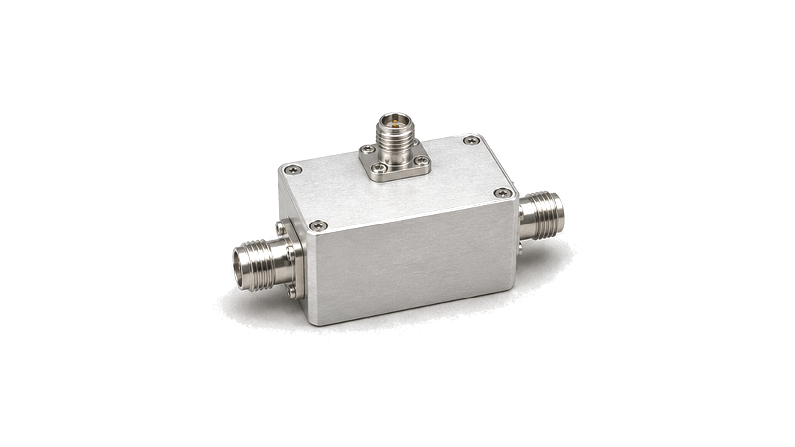
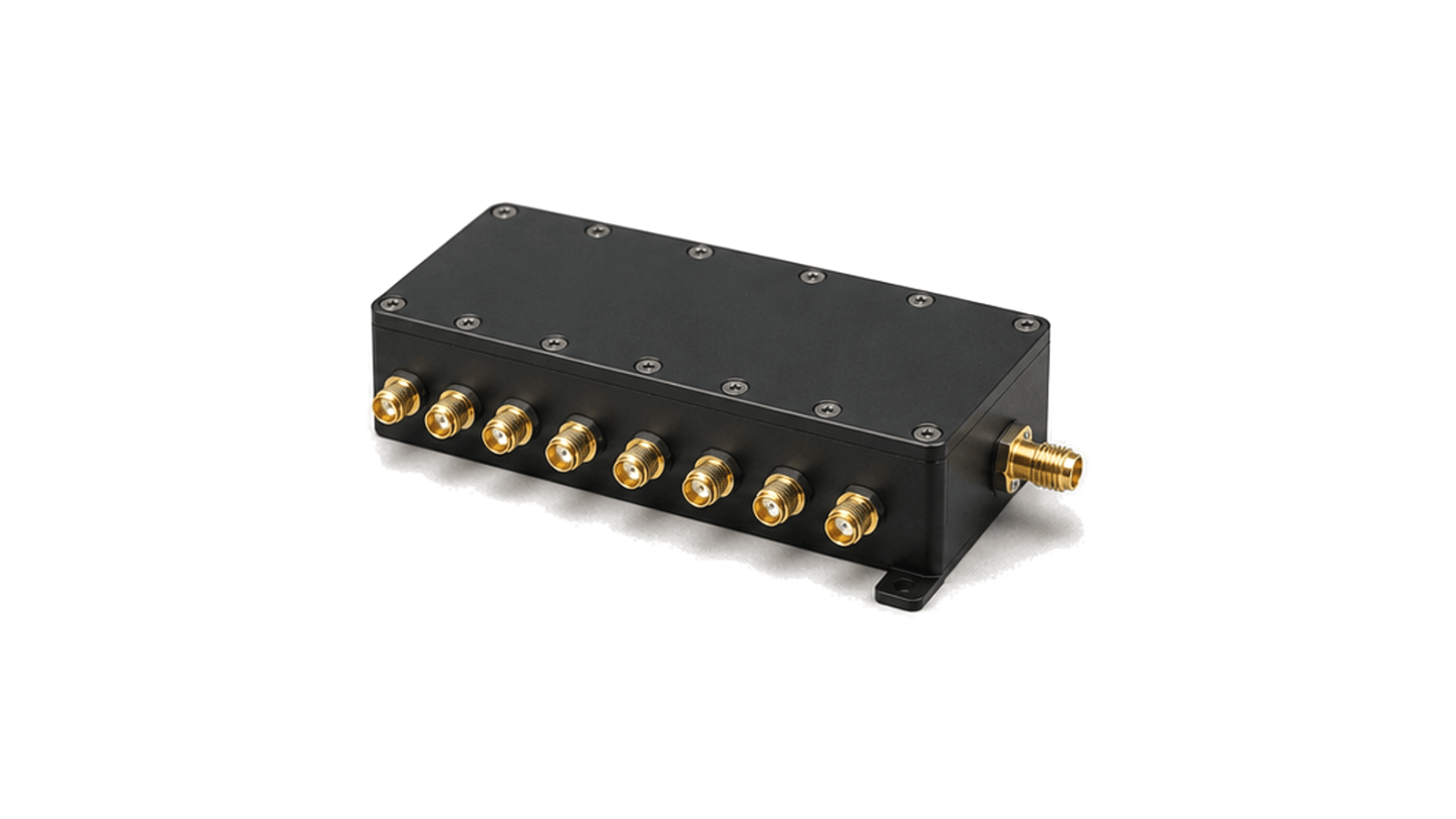
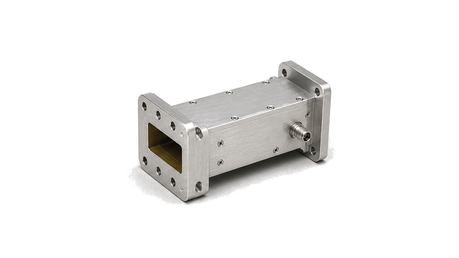
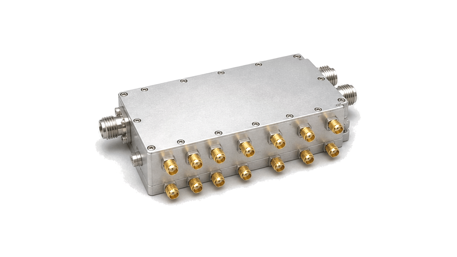
RF filtering and coexistence chain
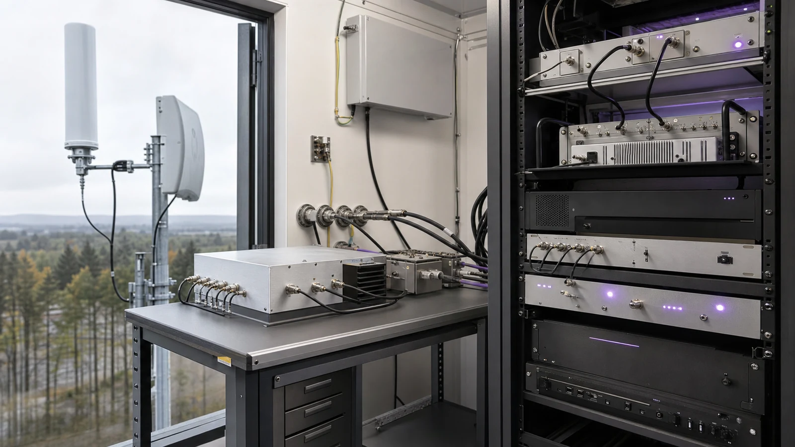
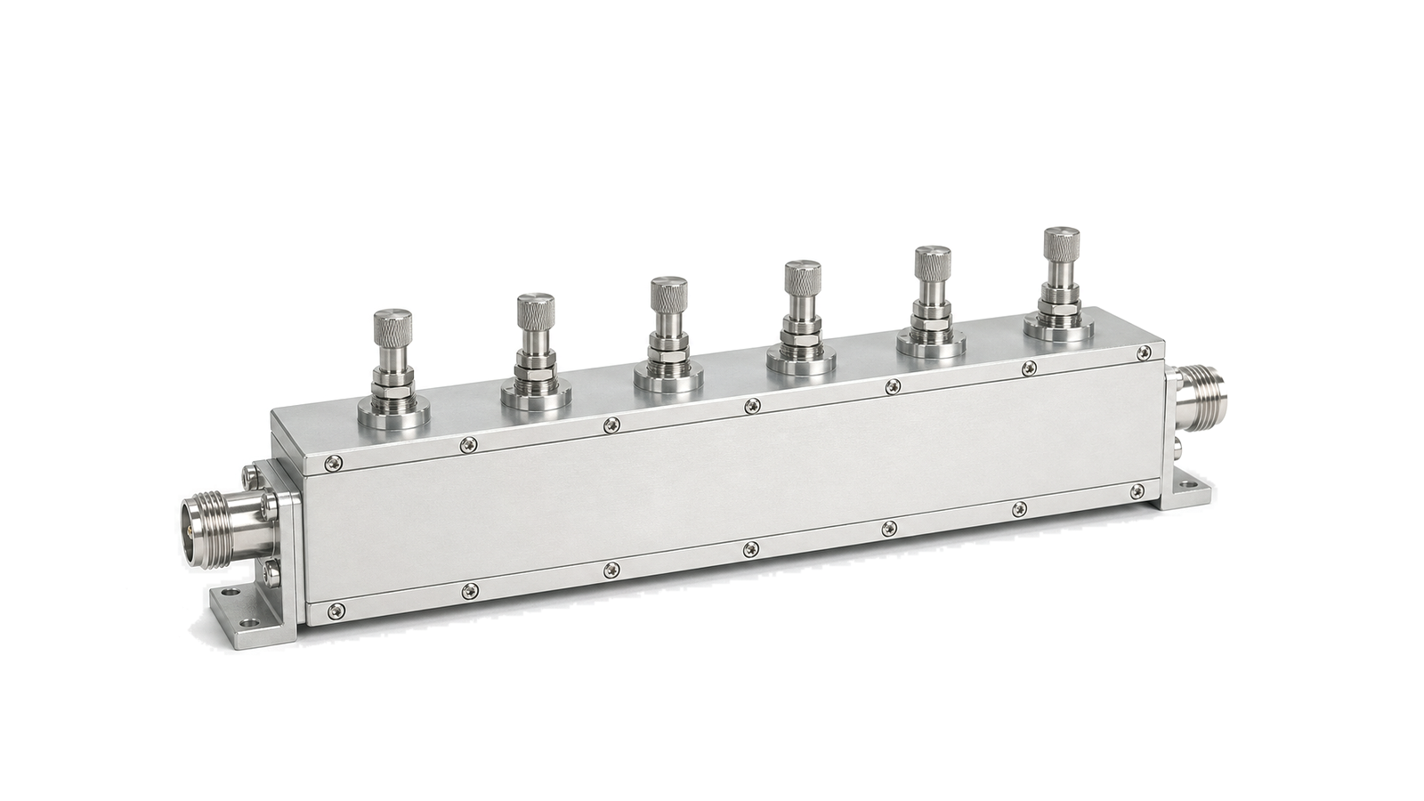
RF filtering and coexistence chains manage how signals share spectrum inside communication, monitoring and pre-compliance systems. Bandpass filters, duplexers, switched filter banks, waveguide filters and RF switches work together to pass the intended band while limiting out-of-band energy.
System boundary
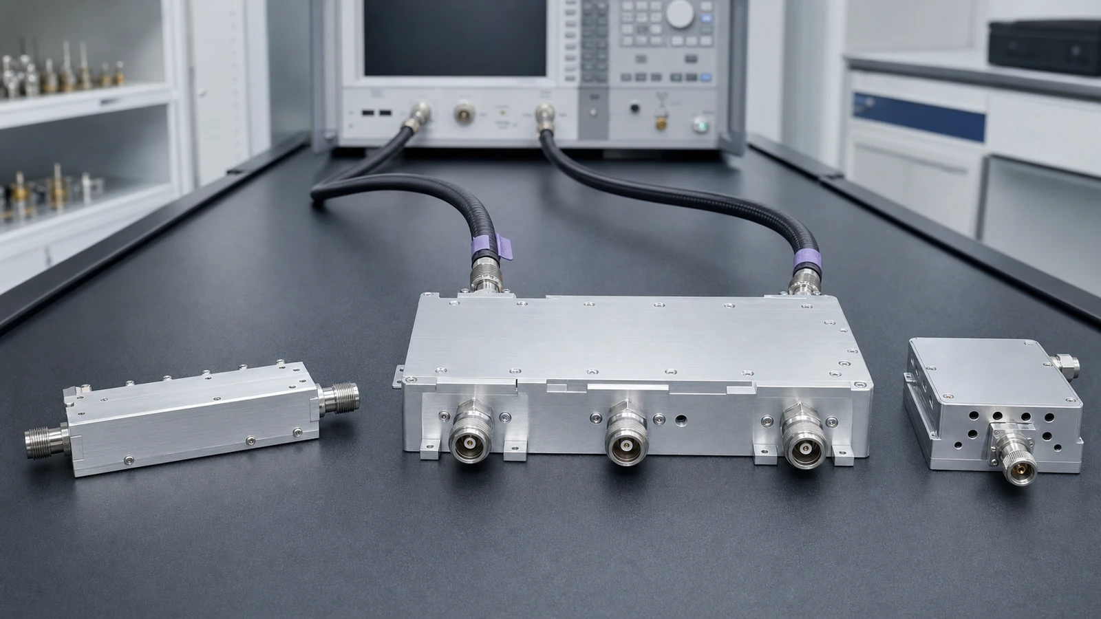
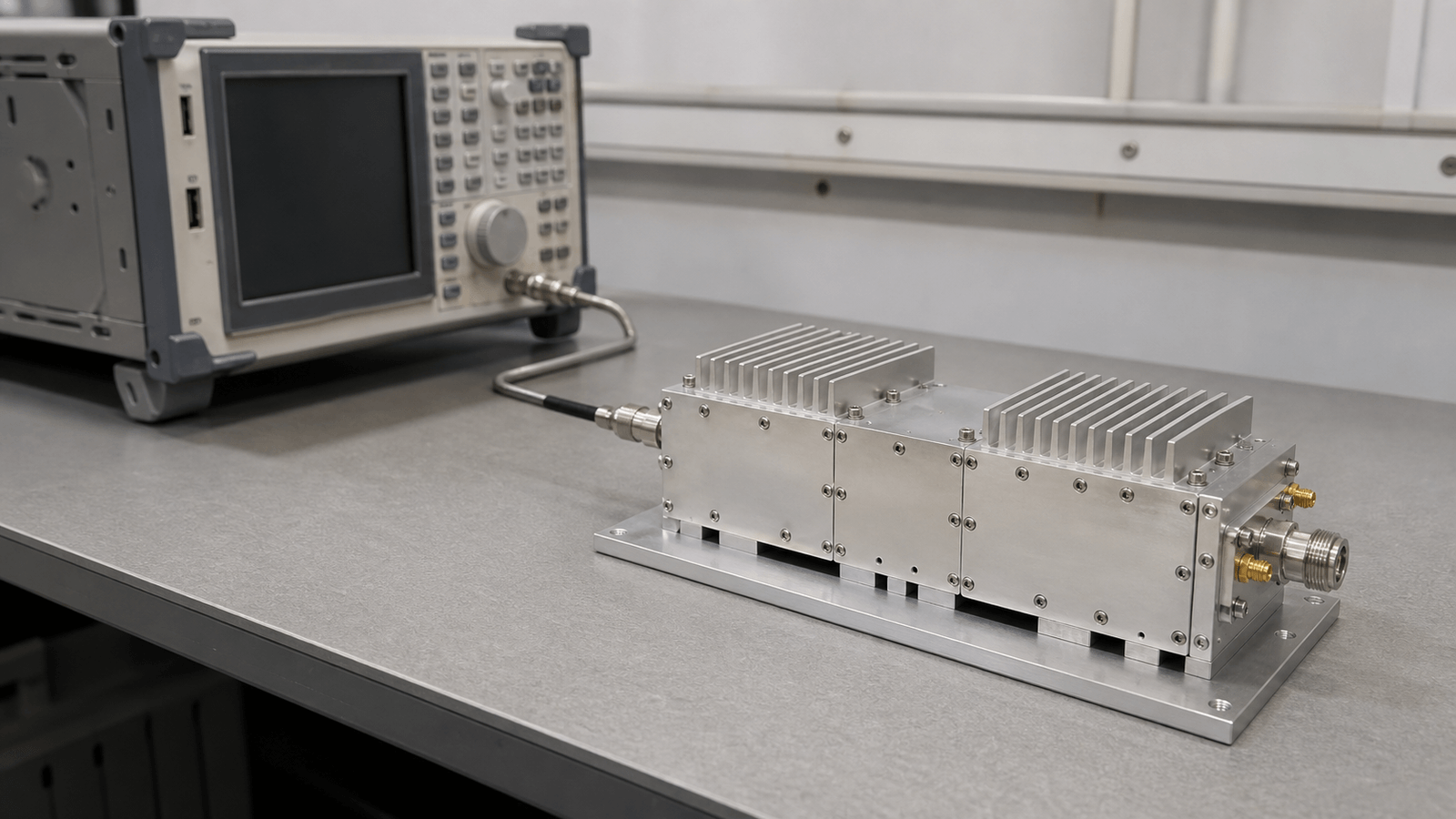
The engineering boundary is defined by passband, rejection, insertion loss, isolation, power handling, switch state and the physical path between antennas, front ends and measurement ports. These values need to be checked under the same interface and load conditions used by the final signal path.
Write the filter requirement as a port-by-port operating mask
- RF Filtering and Coexistence Chain architecture
- Turn the channel plan into a continuous frequency mask
- RF Filtering and Coexistence Chain design requirements
- Keep insertion loss, ripple and return loss as separate decisions
- RF Filtering and Coexistence Chain integration
- Add group-delay or phase-linearity limits only where the waveform needs them
- RF Filtering and Coexistence Chain test and verification
- For duplexers, define isolation with the ports and states that create it
How to Specify an RF Filter or Duplexer: Passband, Rejection, Group Delay and Power
A field-ready method for turning channel plans, blockers, waveform limits, shared-antenna states and thermal conditions into an RF filter or duplexer specification that can be measured and accepted.