
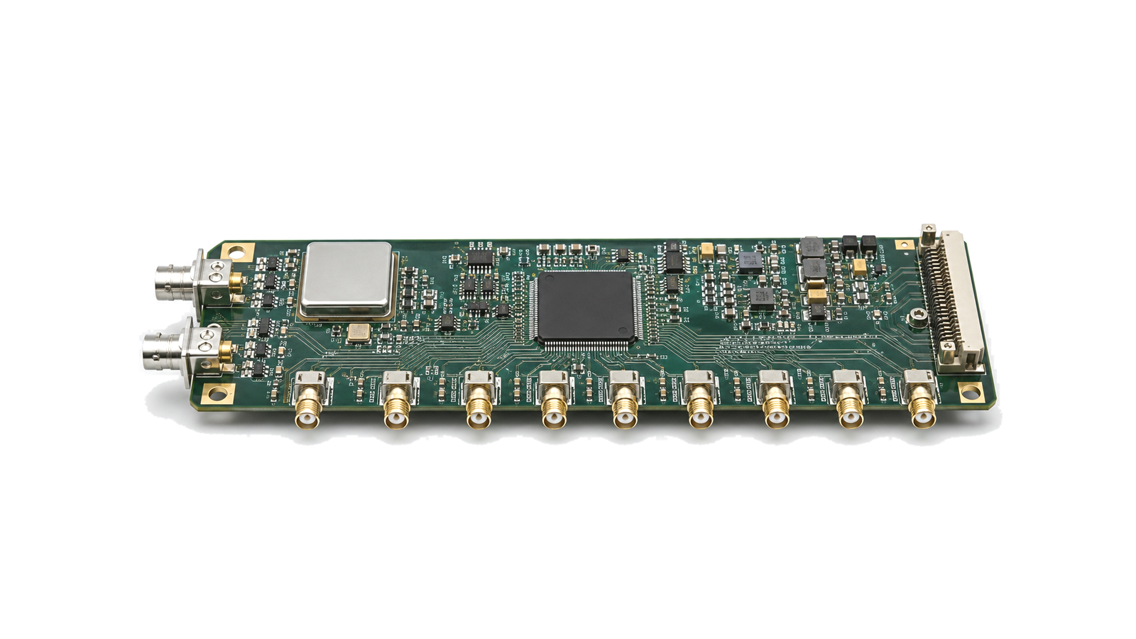
When does an RF timing tree need jitter cleaning rather than simple fanout?
Use fanout when a sufficiently clean reference only needs buffering and format conversion; use a jitter-cleaning PLL when the incoming reference contains phase noise or wander that must be filtered, translated or held through an interruption. The decision depends on noise by offset frequency, not a single jitter number.
Separate distribution, synthesis and synchronization
A fanout buffer reproduces one reference at several outputs and adds finite noise and skew. A synthesizer creates one or more frequencies from a reference. A jitter cleaner uses a PLL and a clean oscillator or VCO to track slow reference behavior while suppressing selected noise. A synchronizer additionally manages deterministic phase, SYSREF, trigger or epoch relationships. Define which functions are inside the module so a low-skew buffer is not expected to repair a noisy source.
Build a phase-noise and jitter budget by offset band
Specify phase-noise limits or integrated RMS jitter with the carrier frequency and integration interval. Close-in reference noise, PLL loop bandwidth, oscillator noise, divider noise, output-buffer floor and spurs dominate different offsets. Additive jitter is measured with a known source and is not the same as total output jitter. Convert the resulting clock uncertainty into converter SNR, sampling aperture or coherent-channel error using the actual input frequency and waveform requirement.
Define reference selection, redundancy and holdover
List accepted input frequencies, levels, formats, termination and lock range, plus priority and switchover rules for redundant references. State whether switching is hitless, phase continuous or allowed to create a controlled transient. Jitter-cleaner loops require acquisition time, loop bandwidth and damping choices. For holdover, define the oscillator, entry condition, allowed frequency or time error, duration, exit behavior and alarms rather than claiming holdover without an error budget.
Specify every output as part of a clock topology
For each output give frequency, format, swing, common-mode, load, coupling and enable state. Include fanout count, output-to-output skew, device-to-device alignment, programmable delay range and step, divider synchronization, duty cycle and crosstalk between unrelated frequencies. Converter systems may need device clock and SYSREF with a deterministic relationship; define whether SYSREF is continuous, pulsed or requested and how runt pulses are prevented.
Preserve clock quality through power and layout
Clock performance depends on supply noise, grounding, output termination, return-current path, connector and cable symmetry, crosstalk and isolation from switching regulators or digital edges. State whether reported jitter is measured at the device pin, module connector or load. Provide the required power filtering, thermal condition and output loading, and avoid unused outputs or improperly terminated branches that change noise and coupling.
Validate lock, noise, skew and deterministic restart
Measure input and output phase noise with documented integration bands, then additive jitter, spurs, output frequency, duty cycle, skew and delay settings. Exercise reference loss, priority switching, holdover, relock and power cycling; verify phase repeatability and SYSREF alignment when deterministic latency matters. Repeat with all outputs active, representative loads, supply and temperature corners. Store analyzer settings, reference source data, cable corrections, loop configuration and pass limits.
RFQ inputs for clock distribution and jitter cleaning
- Input frequency, format, level and phase-noise mask
- Output frequencies, formats, loads and fanout
- RMS jitter integration band or phase-noise limits
- Allowed additive jitter and spurious content
- Output skew, phase alignment and delay adjustment
- PLL architecture, loop bandwidth and acquisition time
- Reference priority, switching and holdover error
- SYSREF, trigger or epoch relationship
- Power, thermal and connector boundary
- Lock, alarm, telemetry and control interface
- Phase-noise, skew and restart acceptance data
Category boundary
This category covers clock fanout, distribution, synchronization and jitter-cleaning assemblies that deliver controlled timing references to RF, converter and digital channels. It excludes standalone crystal oscillators, VCOs, frequency synthesizers, GPS receivers and general timing instruments unless those functions are integrated into the delivered distribution or cleaning module.