
LCRF

Privacy preferences

Choose optional purposes independently. You can change or withdraw your choice at any time from the footer.

Strictly necessary

Required for security, session functions and storing your privacy choice.

Always active
Preferences

Remembers optional display or language settings when these features are enabled.

Analytics

Uses first-party visitor and session identifiers to measure pages, referrals and inquiry interactions.

Marketing

Allows marketing measurement or third-party advertising technologies if they are introduced in the future.

EMC / EMI Pre-Compliance

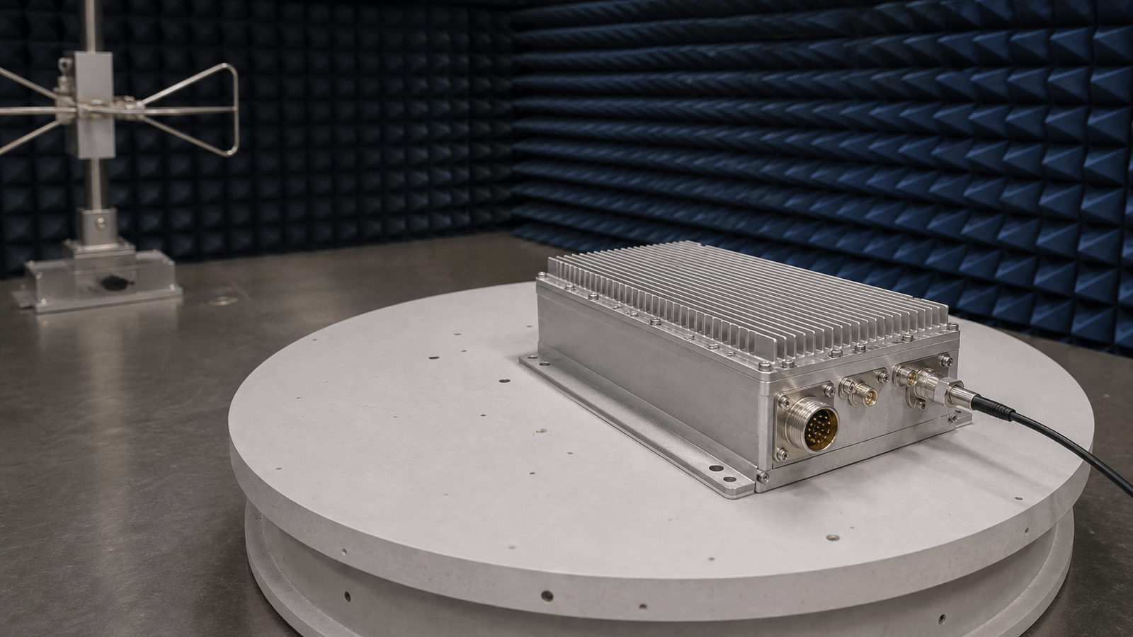
EMC and EMI pre-compliance work checks conducted and radiated behavior before formal certification, using repeatable RF paths, probes, fixtures, filters and measurement receivers.

EMC / EMI Pre-Compliance RF application visual

Early RF emission and immunity checks

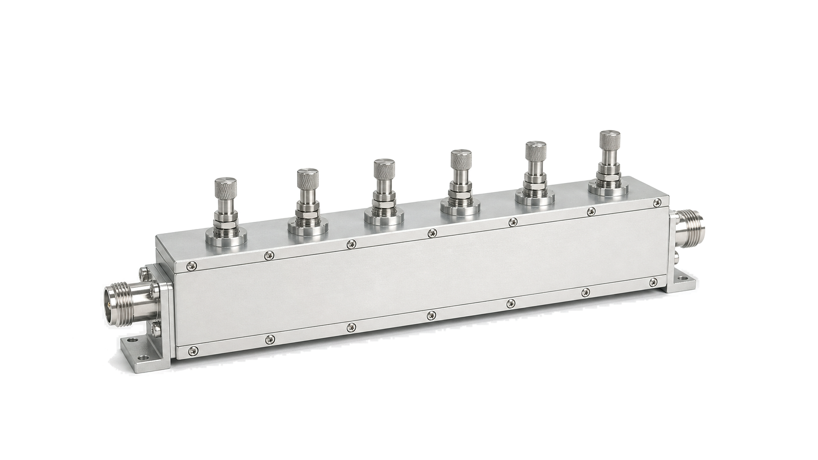
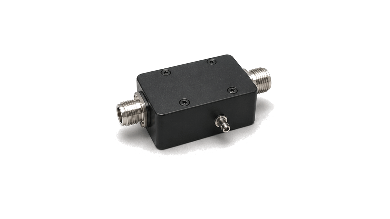
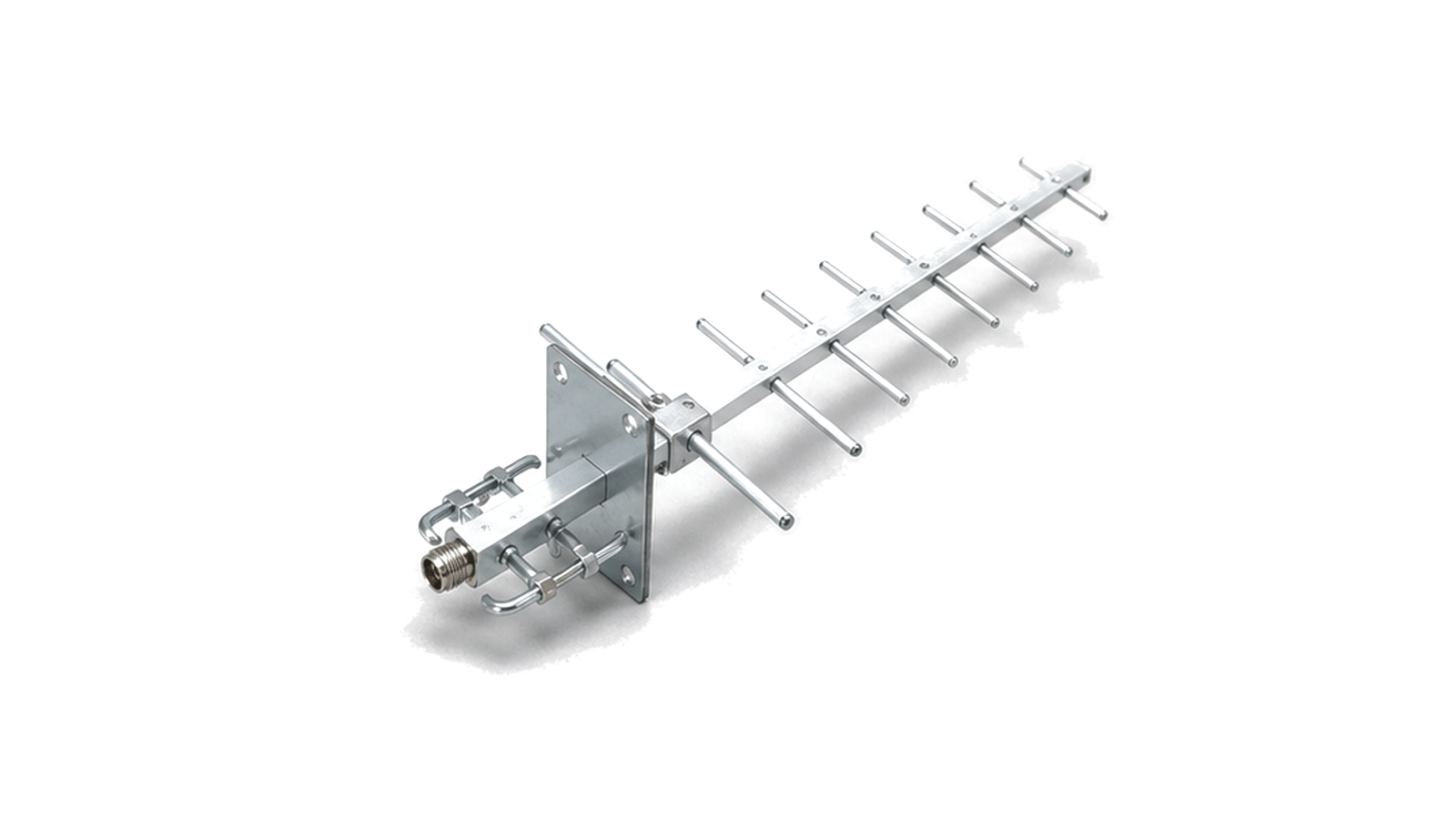
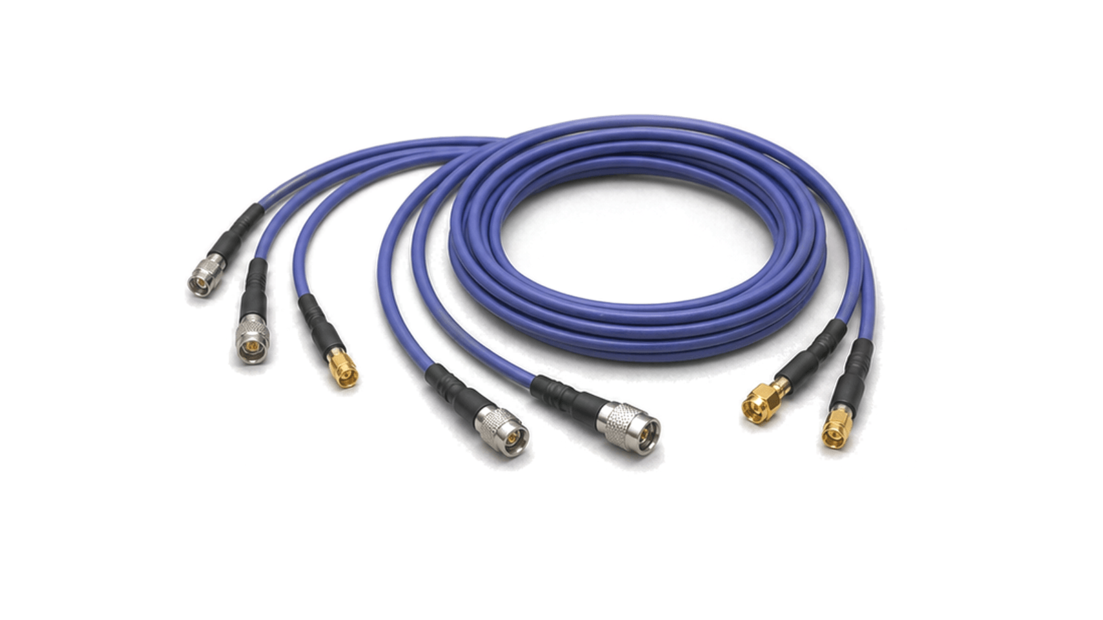
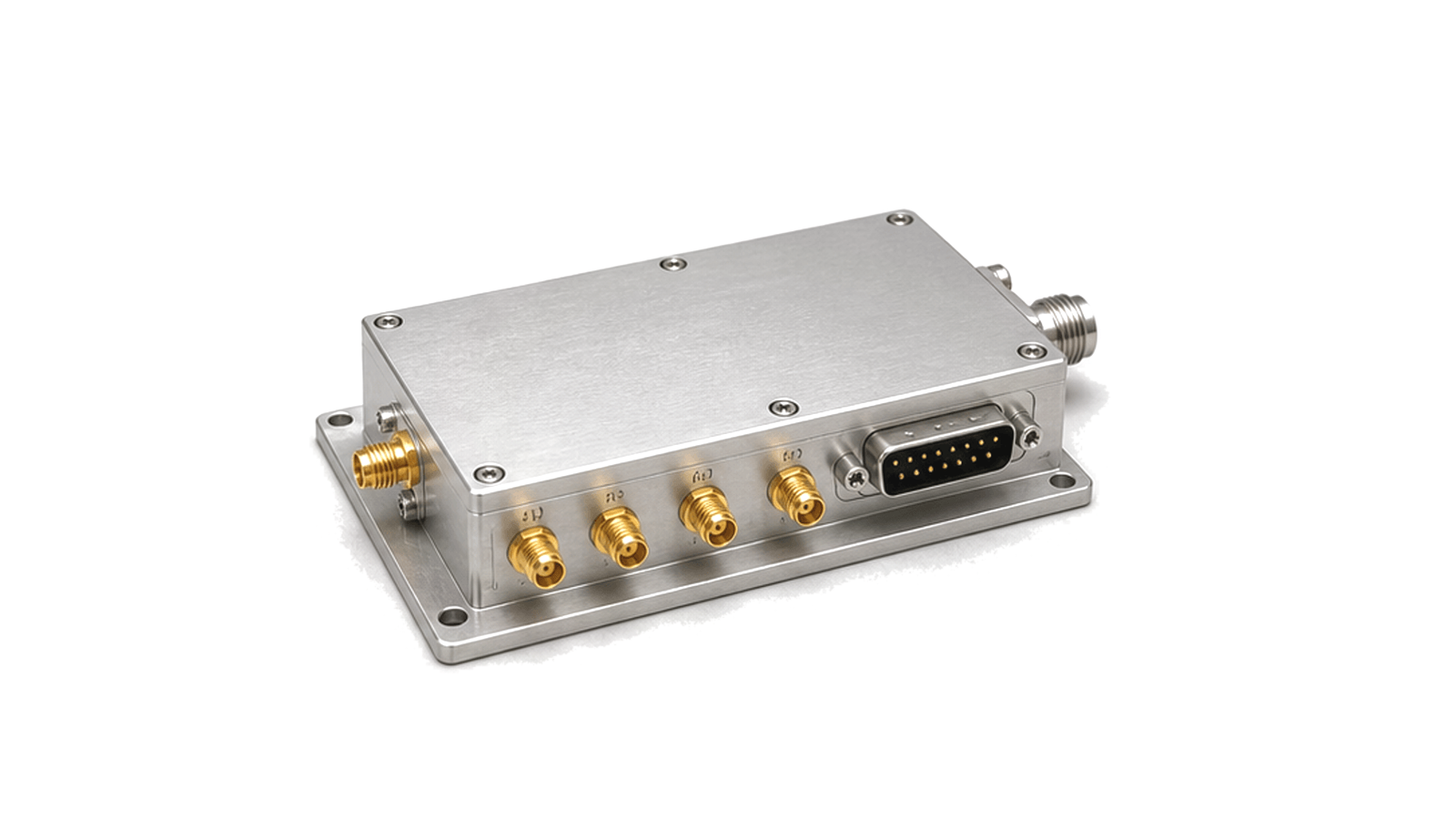
EMC and EMI pre-compliance work is used before a product enters formal certification. The RF path may include probes, attenuators, filters, switch paths, calibrated cables, fixtures and measurement receivers to identify emissions, coupling paths or immunity concerns while the design can still be changed.

Measurement context

Useful data includes frequency span, detector mode, probe type, fixture setup, reference level, attenuation, filter bandwidth, cable loss, grounding condition and repeatability between test runs.

What RF hardware is required for EMC / EMI Pre-Compliance?

EMC and EMI pre-compliance work checks conducted and radiated behavior before formal certification, using repeatable RF paths, probes, fixtures, filters and measurement receivers.

How is an RF signal chain designed for EMC / EMI Pre-Compliance?

An engineering method for selecting and installing RF absorber by field problem, frequency, material form, thickness, metal backing, incidence, reflectivity, power density, environment and installed evidence.

  • How should RF absorber be selected and installed?
  • Engineering path
  • Name the unwanted field path before choosing a material

Which RF specifications matter for EMC / EMI Pre-Compliance?

Useful data includes frequency span, detector mode, probe type, fixture setup, reference level, attenuation, filter bandwidth, cable loss, grounding condition and repeatability between test runs.

How do you test and verify RF hardware for EMC / EMI Pre-Compliance?

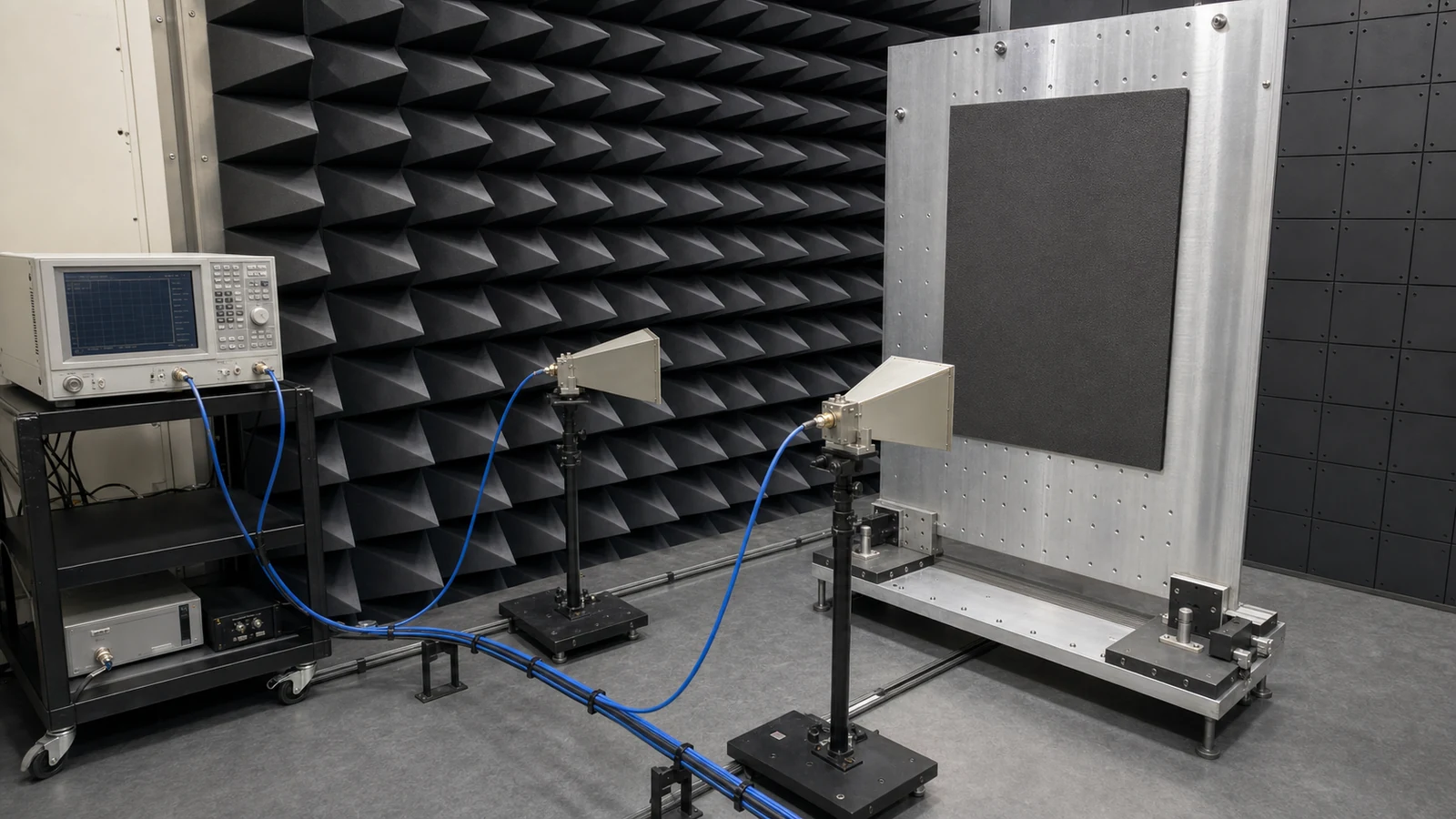
Select RF absorber by defining the unwanted electromagnetic path first: free-space reflection, chamber echo, cavity resonance, near-field coupling or aperture leakage. Then freeze frequency, incidence angle, polarization, available thickness, metal backing, required reflectivity or attenuation, average and peak power density, temperature and environment. Compare materials only with test data from the same geometry and reference method.
RF Absorber Selection, Placement and Verification

Articles

FAQ

How should connector and fixture repeatability, wear and maintenance be controlled?

Control RF test-hardware repeatability with inspection, cleaning, gauging, specified torque, fixed mechanical datums, remate checks and lifecycle limits for connectors, clamps and probes.

What is an RF measurement reference plane, and when is fixture de-embedding required?

The measurement reference plane is the electrical boundary where a corrected value is claimed; de-embedding is needed only when a characterized fixture network must be removed to report at a different DUT plane.

Which calibration-kit data and traceability records should accompany RF measurement hardware?

Keep the physical standards tied to the correct kit definition, serial identity, coefficient files, certificate, environmental condition and uncertainty chain used for the reported result.

How is RF absorber reflectivity and installed performance tested and verified?

Absorber verification needs a calibrated coupon method plus a repeatable installed before-and-after measurement using the same geometry and operating state.

How do frequency, thickness and metal backing affect RF absorber selection?

Absorber thickness and backing are part of the electromagnetic stack; frequency, incidence, polarization and available depth determine which material form can be evaluated.

How should RF absorber power handling, temperature, flame and outgassing be specified?

Power and environmental limits apply to the exact absorber, adhesive, coating, airflow and exposure duration rather than to a material family name.

Engineering inquiry

Share your RF requirement

Share the product, operating requirements and project context. Our engineering team will route your request to the right specialist.

AttachmentsAttach drawings, BOMs, specifications or test files. Up to 5 files, 10 MB each and 25 MB total.
or drag and dropPDF, DOCX, XLSX, CSV, TXT, JPG, PNG, S1P and S2P
Typically reviewed within one business dayProject information is handled confidentially