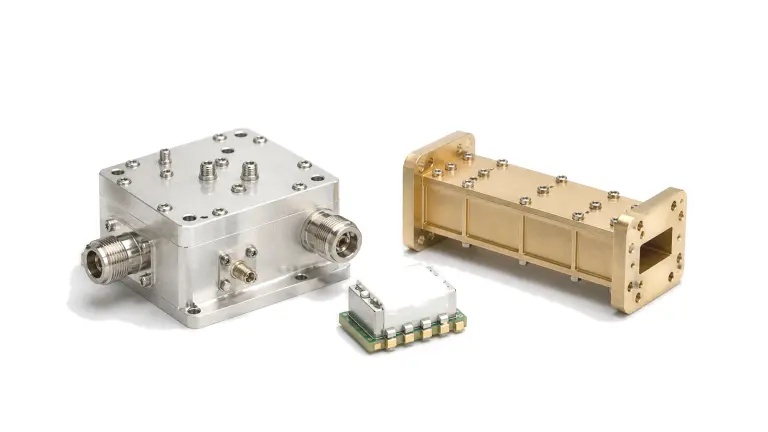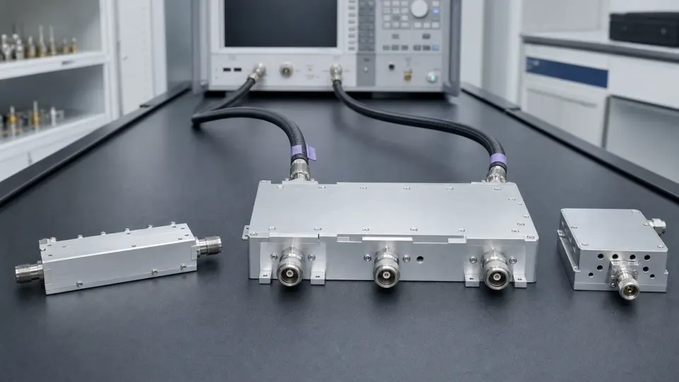
Write the filter requirement as a port-by-port operating mask
A filter or duplexer is acceptable only when every required path meets its loss, matching, phase, rejection and power limits at declared ports and operating states. Name the source and load impedances, connector planes, frequency grid, temperature, drive level and unused-port terminations. For a multiport device, state which transmitter, receiver and antenna paths are active simultaneously. This prevents a favorable two-port trace from being mistaken for proof of system coexistence.
Turn the channel plan into a continuous frequency mask
Begin with frequencies that must pass, frequencies that may transition and frequencies that must be rejected. A statement such as ‘2.4 GHz band-pass filter’ leaves the usable bandwidth, guard bands and blockers unresolved. Define passband edges with worst-case insertion loss and ripple; define stopbands as continuous ranges with minimum attenuation; and identify narrow exceptions only when the system can tolerate them. Include manufacturing tolerance and temperature movement rather than placing the required edge on a nominal resonance.
The mask must reflect the actual source and victim. In a receiver, a blocker close to the wanted band can set the transition slope and rejection. In a transmitter, harmonics, image products or adjacent carriers may set far-out attenuation. In a duplexer, transmit leakage at the receive port is an isolation problem under a simultaneous operating state, not simply a catalog stopband number. State whether limits apply to every unit or describe a typical trace; procurement decisions require maximum or minimum boundaries.
Keep insertion loss, ripple and return loss as separate decisions
Insertion loss is the transmitted-power reduction through the intended path relative to the defined reference planes. Return loss describes mismatch at one port while the other ports are terminated as specified. They interact in a system but cannot replace one another: a path can show acceptable transmission and poor matching, or good matching and excessive dissipative loss. Record both versus frequency, temperature and relevant power state. For receiver paths, place filter loss before or after the first low-noise stage in the actual noise-figure budget; a passive loss ahead of the LNA directly consumes sensitivity.
Passband flatness or ripple matters when gain calibration, amplitude accuracy or multicarrier balance is tight. Do not hide a sharp edge excursion inside an average loss figure. If cable or fixture loss is removed, name the de-embedding method and preserve the raw measurement. A supplier trace referenced at an internal launch cannot be compared directly with a system limit at the external connector unless the intervening adapters and transitions are accounted for.
Add group-delay or phase-linearity limits only where the waveform needs them
Group delay is derived from the slope of transmission phase with frequency. Large variation across the occupied signal band can spread a pulse, disturb symbol timing or rotate subcarriers differently even when amplitude loss looks flat. Define the occupied or analysis bandwidth, reference delay, allowed peak-to-peak ripple and smoothing or aperture used to calculate the trace. The useful phase-linear band may be narrower than the amplitude passband, especially near steep skirts.
Do not demand an arbitrary low group-delay ripple across the entire catalog passband. Tie it to pulse width, modulation bandwidth, EVM, ranging accuracy or channel equalization capability. If constant delay can be calibrated out, specify variation rather than absolute delay. If the system compares channels, include differential delay and temperature tracking between paths.
For duplexers, define isolation with the ports and states that create it
A duplexer or multiplexer has more than one transmission path, so ‘rejection’ is ambiguous without a source port, destination port and termination state. Define antenna-to-receive loss, transmit-to-antenna loss, transmit-to-receive isolation, cross-band isolation and return loss at every port. State whether the other transmitter is on, whether the antenna port sees its expected mismatch, and whether switching, tuning or filter-bank state changes the result.
Isolation must close a power budget. Subtract the minimum isolation from the maximum transmitter level at the same reference planes, then compare the residual leakage with the receiver’s blocker, compression, damage and desensitization limits. Add leakage from switches, circulators, cables, enclosures and board coupling; a component isolation number alone does not prove the assembled front end will coexist.
Translate insertion loss into heat before accepting a power rating
Power handling is not a connector label. The dissipated fraction rises with insertion loss, and local current or voltage peaks can cause heating, arcing, dielectric stress, compression or passive intermodulation before the average connector power appears extreme. Define CW, peak and average power, pulse width, duty cycle, crest factor, mismatch phase, reverse power, ambient temperature, baseplate temperature, airflow and mounting. For multiport devices, include simultaneous carriers and terminations.
Temperature changes conductor loss, dielectric behavior and resonant frequency; it can move the passband while reducing thermal margin. Require the frequency mask after thermal equilibrium at the declared power, not only in a low-level room-temperature sweep. Where PIM matters, state carrier frequencies, tone powers, order, receive bandwidth and test-fixture residual floor.
| Decision block | Requirement to freeze | Reject the proposal when |
|---|---|---|
| Frequency response | Usable passband, ripple, transitions, continuous stopband masks and temperature tolerance | Only center frequency and nominal bandwidth are stated |
| Ports and matching | Reference planes, impedance, terminations, S-parameters and return-loss limits | Trace planes or unused-port states are undefined |
| Waveform fidelity | Occupied band, group-delay ripple, phase linearity or differential delay | A flat amplitude trace is treated as proof of low distortion |
| Duplex operation | Every source-destination port pair, simultaneous state and isolation budget | One rejection point is used for all paths and operating states |
| Power and environment | CW/pulse levels, duty cycle, mismatch, temperature, cooling, PIM and post-soak mask | Power rating omits loss, mounting or thermal conditions |
| Verification | Calibration, fixture removal, source power, IF bandwidth, dynamic range, uncertainty and retained files | Deep rejection is reported at the analyzer noise floor |
Worked check: a small insertion loss can become a large thermal load
A 100 W CW signal entering a filter with 0.8 dB insertion loss delivers about 83.2 W to the load because 10-0.8/10 = 0.832. Roughly 16.8 W is therefore not delivered. Some is reflected according to the input match; the remainder is dissipated inside the filter and transitions. The thermal design must remove that heat while the passband and rejection mask remain compliant. This calculation is a screening check, not a power rating: mismatch, field concentration, pulse peaks, enclosure temperature and PIM can impose lower limits.

Verify the complete mask without measuring the test set
- Draw every connector, adapter, fixture and calibration plane; terminate unused ports in the specified impedance.
- Choose a full two-port or multiport calibration that reaches the required planes, then save verification standards and raw S-parameters.
- Use enough VNA source power for rejection dynamic range without compressing, heating or tuning the device.
- Segment the sweep so passband resolution, transition detail and stopband noise floor each receive suitable IF bandwidth and averaging.
- Measure magnitude and phase together; calculate group delay with a declared aperture over the actual occupied band.
- Repeat the required port combinations, switch states, antenna mismatch states and simultaneous transmit conditions.
- Run low-level temperature sweeps and separate high-power thermal, compression, breakdown or PIM tests where required.
- Retain calibration state, fixture model, source level, limits, uncertainty, Touchstone data and failed traces for production correlation.
Specification failures that surface late in integration
- Using a nominal 3 dB bandwidth where the system needs a guaranteed low-loss usable band.
- Quoting rejection at one frequency instead of a continuous blocker or emission mask.
- Treating insertion loss and return loss as interchangeable.
- Ignoring group-delay ripple because the amplitude passband looks flat.
- Calling a duplexer isolation value complete without source and destination ports.
- Testing deep rejection with insufficient calibrated dynamic range.
- Accepting a room-temperature small-signal trace for a high-power operating state.
- Omitting unused-port termination, antenna mismatch, cable coupling or enclosure leakage.
Information required for an RF filter or duplexer RFQ
- Passbands, usable edges, transition regions, stopband masks, guard bands and frequency tolerance
- Port count, connector or package, impedance, reference planes and unused-port terminations
- Maximum insertion loss, passband ripple and return loss for each path
- Group-delay ripple, phase linearity or differential-delay limits over the occupied band
- Duplexer path matrix, simultaneous states, transmitter level and receiver leakage limit
- CW, peak and average power, pulse width, duty cycle, mismatch, reverse power and PIM conditions
- Ambient and baseplate temperature, mounting, airflow, shock, vibration and sealing requirements
- VNA calibration, source level, dynamic range, uncertainty, temperature/power tests and required data files