
LCRF

Privacy preferences

Choose optional purposes independently. You can change or withdraw your choice at any time from the footer.

Strictly necessary

Required for security, session functions and storing your privacy choice.

Always active
Preferences

Remembers optional display or language settings when these features are enabled.

Analytics

Uses first-party visitor and session identifiers to measure pages, referrals and inquiry interactions.

Marketing

Allows marketing measurement or third-party advertising technologies if they are introduced in the future.

RF Limiters

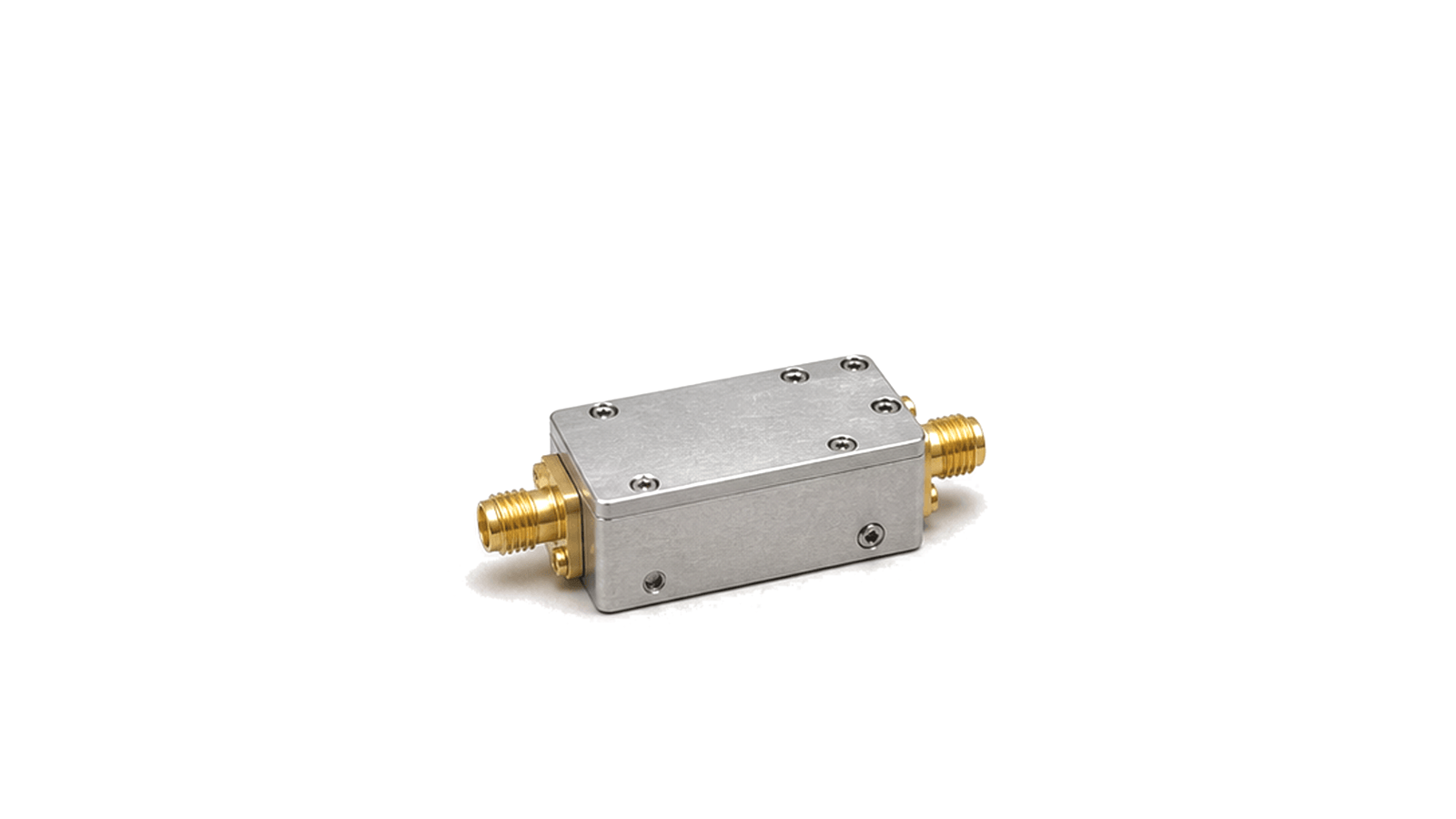
Antenna-facing hardware starts with radiation geometry. RF Limiters sits within Attenuation, Detection & Monitoring and converts RF level information into a monitoring or protection signal. The content focuses on dynamic range, video bandwidth, detection slope, response time and input power limit for engineers, sourcing teams and system integrators.

RF Limiters

FAQ

What must a radar Tx/Rx protection requirement include beyond receiver survival?

A complete Tx/Rx protection requirement includes survivable peak and average leakage, limiter and switch behavior, residual level, overload recovery, post-pulse gain/noise/phase and the nearest usable range gate.

How should RF P1dB and two-tone intermodulation tests differ?

P1dB is a single-tone gain-compression sweep, while two-tone IMD measures nonlinear mixing products with stated tone spacing, per-tone power and system residual checks; the results answer different questions.

Engineering inquiry

Share your RF requirement

Share the product, operating requirements and project context. Our engineering team will route your request to the right specialist.

AttachmentsAttach drawings, BOMs, specifications or test files. Up to 5 files, 10 MB each and 25 MB total.
or drag and dropPDF, DOCX, XLSX, CSV, TXT, JPG, PNG, S1P and S2P
Typically reviewed within one business dayProject information is handled confidentially

RF Limiters

Antenna-facing hardware starts with radiation geometry. RF Limiters converts RF level information into a monitoring or protection signal for power monitoring, receiver protection, pulse measurement and closed-loop RF control. The information is organized around how this hardware is used in an RF system.

Key data centers on dynamic range, video bandwidth, detection slope, response time and input power limit. Those details help engineering, sourcing and integration teams compare the record against the actual signal path, mechanical boundary and operating environment.

When reviewed with model data, outline dimensions, test conditions and delivery documents, the content makes project scope, constraints and follow-up verification points easier to align early.