
LCRF

Privacy preferences

Choose optional purposes independently. You can change or withdraw your choice at any time from the footer.

Strictly necessary

Required for security, session functions and storing your privacy choice.

Always active
Preferences

Remembers optional display or language settings when these features are enabled.

Analytics

Uses first-party visitor and session identifiers to measure pages, referrals and inquiry interactions.

Marketing

Allows marketing measurement or third-party advertising technologies if they are introduced in the future.

Phase-Coherent Timing Chain

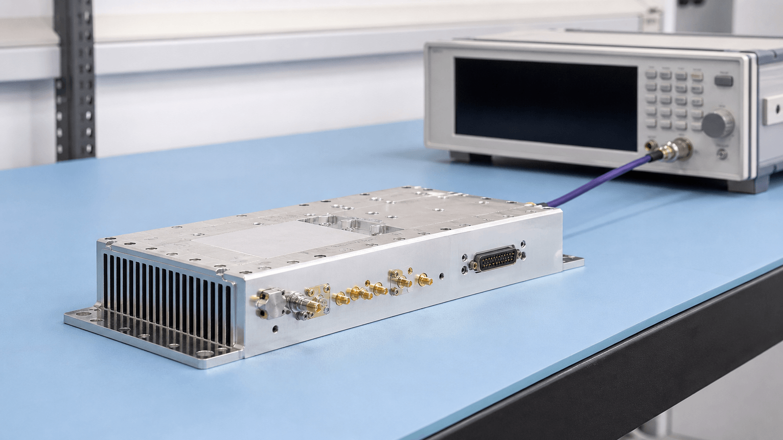
Phase-coherent timing chains distribute a shared reference, clock or synthesized source across RF paths that must keep a known phase relationship. They appear in phased arrays, coherent radar, frequency-conversion benches and synchronized RF instruments.

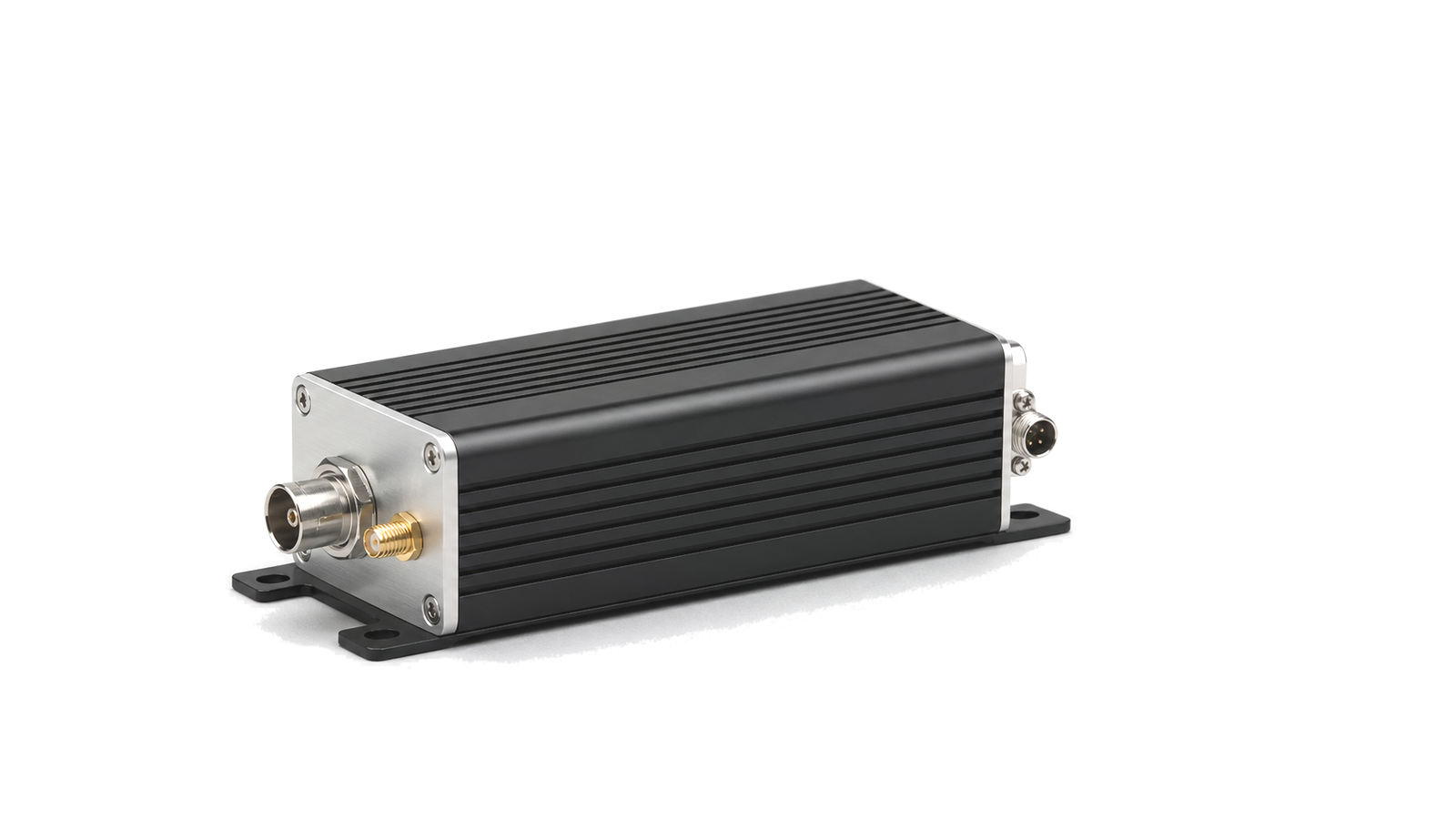
Phase-Coherent Timing Chain RF solution visual

Phase-Coherent Timing Chain

A phase-coherent timing chain keeps multiple RF paths tied to the same reference, clock or synthesized source. The chain is used when channels must preserve a defined phase relationship instead of operating as independent frequency paths.

Timing path scope

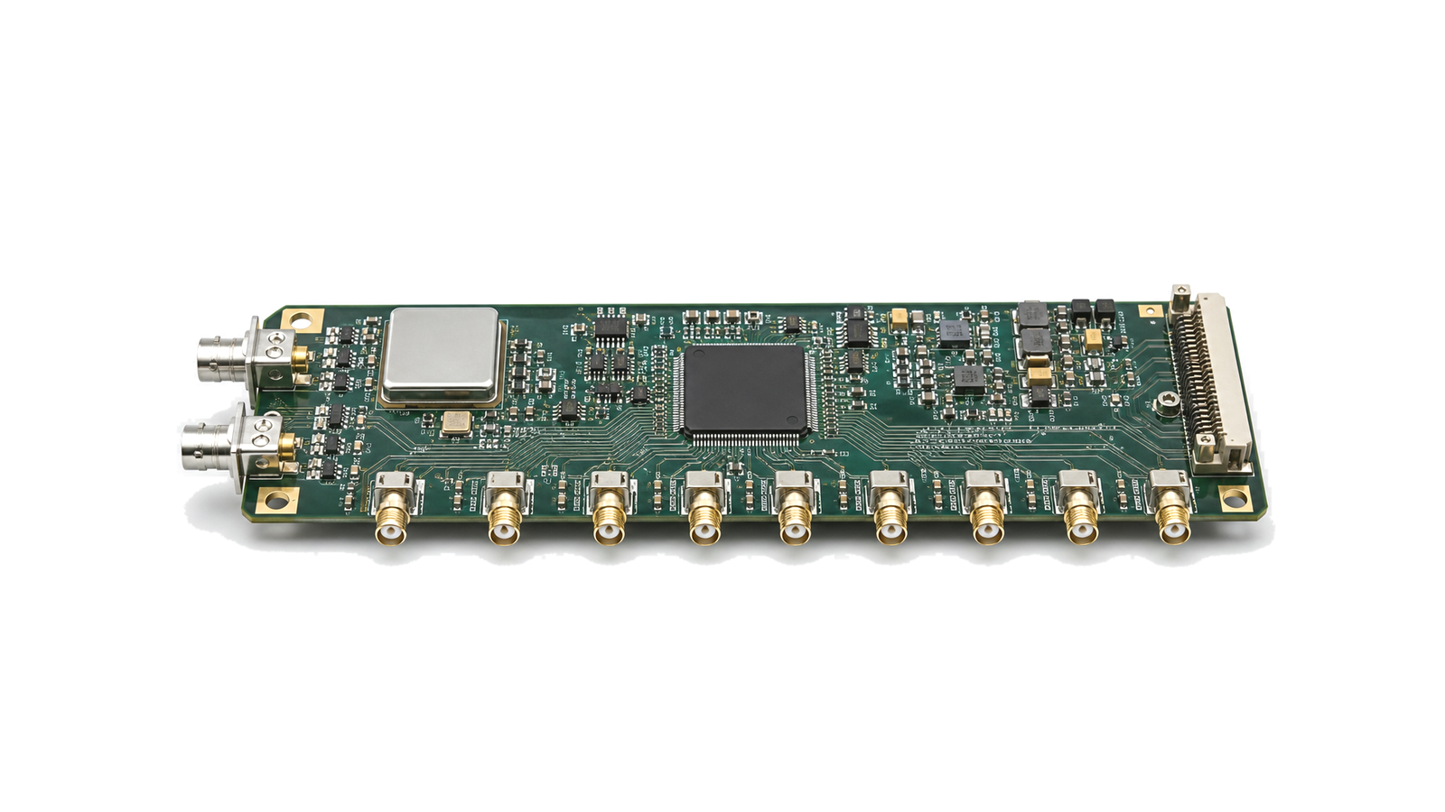
The path may include an OCXO reference, frequency synthesizer, clock distribution module, low-loss interconnect and controlled routing to LO inputs, converters, array elements or synchronized instruments. The useful boundary is the point where phase noise, jitter, skew, cable loss and channel delay can be measured and held within the system budget.

Data normally reviewed

Reference frequency, stability and aging, phase-noise offsets, jitter, output level, fan-out, connector type, cable length, lock status and channel-to-channel delay are usually kept together so the timing path can be compared without separating source data from distribution data.

Treat reception and timing as one evidence chain

Phase-Coherent Timing Chain architecture
Define the service, operating environment and loss-of-signal behavior
Phase-Coherent Timing Chain design requirements
Freeze the antenna-to-receiver reference plane
Phase-Coherent Timing Chain integration
Allocate weak-signal margin and blocker tolerance together
Phase-Coherent Timing Chain test and verification
Separate acquisition, discipline, holdover and recovery

How to Specify a GNSS Receiver Front End and Precision Timing Chain

A practical method for defining GNSS and BeiDou antenna paths, filtering, low-noise gain, receiver interference tolerance, disciplined references, holdover and PPS or 10 MHz distribution with measurable acceptance evidence.
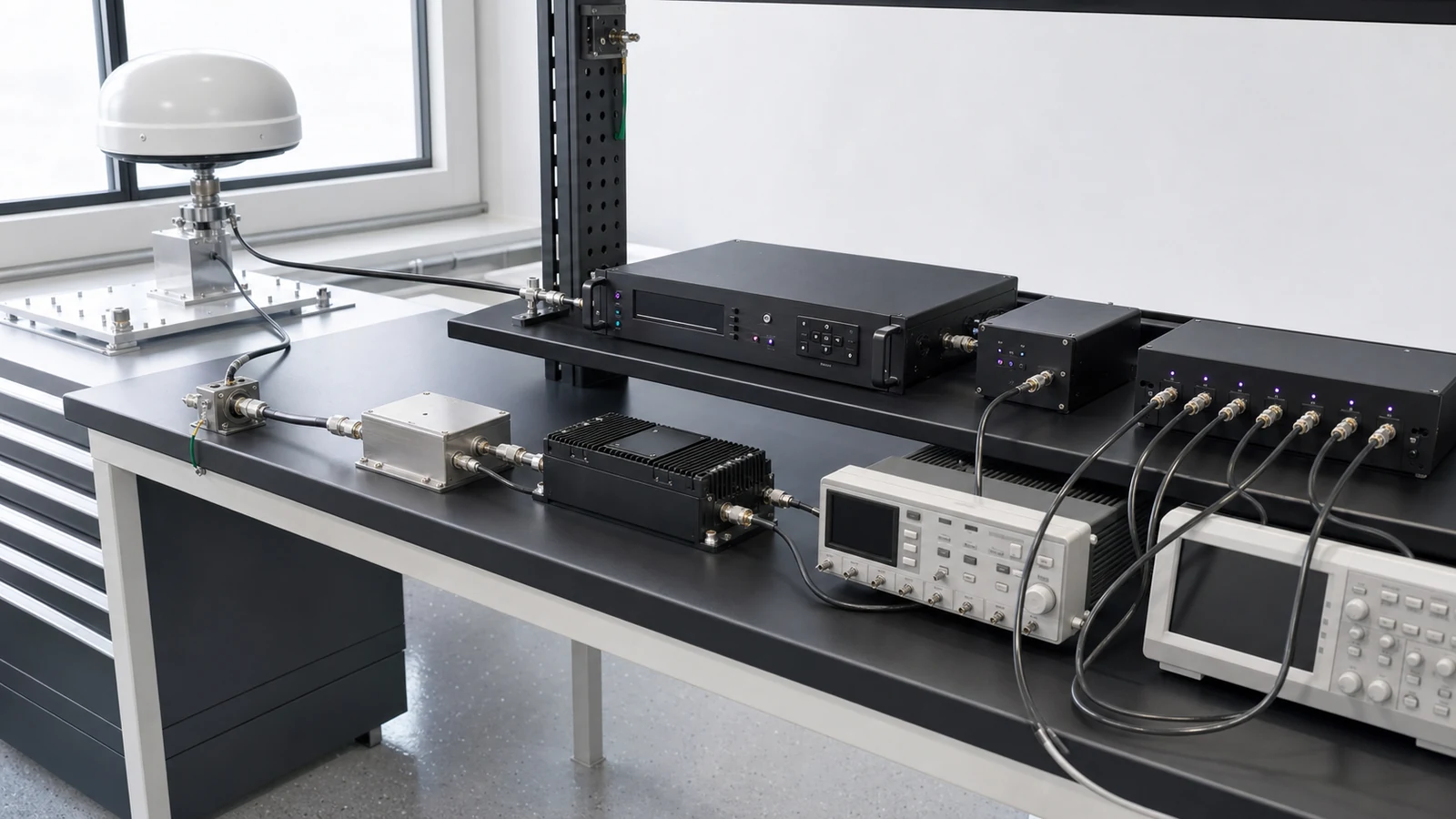
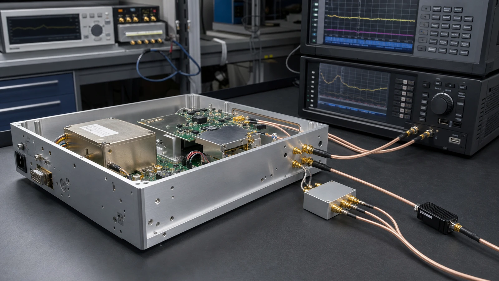
GNSS RF Front-End & Precision Timing Specification

Articles

FAQ

Does sharing a frequency reference make multiple RF sources phase coherent?

A shared reference aligns average frequency, but deterministic relative phase also depends on trigger timing, divider state, path delay, retune behavior, relock and restart conditions.

How should PPS and 10 MHz timing-distribution delay and skew be verified?

Verify every delivered timing channel at its real load by separating fixed calibrated delay, channel skew, environmental drift, output level, edge or phase behavior and path-dependent uncertainty.

How should GNSS receiver blocker and interference tolerance be specified?

Define the interferer waveform, frequency, bandwidth, duty cycle, coupling plane, wanted-signal state, exposure and measurable degradation or recovery metric instead of relying on an anti-jam label.

What belongs in a GNSS antenna, LNA, filter and cable RF budget?

Budget antenna gain, pre-LNA loss, LNA noise and gain, filtering, cable loss, active-antenna power, return loss, linearity, receiver range and blocker headroom in physical path order.

What does holdover mean in a GNSS-disciplined timing system?

Holdover is the bounded time or frequency performance after GNSS reference loss, defined by the starting state, outage duration, environment, local oscillator, steering history, maximum time error and recovery rule.

When should an RF source use phase-noise spot limits versus integrated jitter?

Use phase-noise spot or mask limits when offset regions drive RF behavior; use integrated jitter only when the project defines the integration band and a time-domain error budget.

What does PLL settling time mean, and why is lock detect not enough?

PLL settling time is the time from a defined disturbance until the RF output enters and remains inside specified frequency, phase, amplitude and spectral limits; lock detect is only an internal status signal.

How should frequency accuracy, temperature stability, aging and holdover be specified?

Specify accuracy, temperature, aging and holdover as separate error terms with their own interval, environment, warm-up and reference history instead of one unexplained ppm value.

Engineering inquiry

Share your RF requirement

Share the product, operating requirements and project context. Our engineering team will route your request to the right specialist.

AttachmentsAttach drawings, BOMs, specifications or test files. Up to 5 files, 10 MB each and 25 MB total.
or drag and dropPDF, DOCX, XLSX, CSV, TXT, JPG, PNG, S1P and S2P
Typically reviewed within one business dayProject information is handled confidentially