
LCRF

Privacy preferences

Choose optional purposes independently. You can change or withdraw your choice at any time from the footer.

Strictly necessary

Required for security, session functions and storing your privacy choice.

Always active
Preferences

Remembers optional display or language settings when these features are enabled.

Analytics

Uses first-party visitor and session identifiers to measure pages, referrals and inquiry interactions.

Marketing

Allows marketing measurement or third-party advertising technologies if they are introduced in the future.

RF Component Characterization

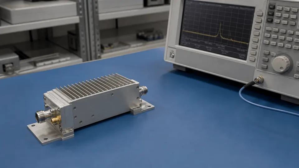
RF component characterization measures individual devices and modules on controlled benches before they are placed into larger signal chains.

RF Component Characterization RF application visual

RF Component Characterization

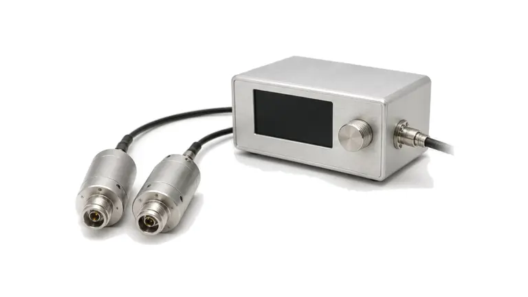
RF component characterization measures individual devices, modules and small assemblies on a controlled bench before they are integrated into a larger signal chain. The work may cover S-parameters, gain, loss, compression, power handling, detector response, coupling behavior and temperature sensitivity.

Bench boundary

The bench must define reference planes, connector interfaces, cable movement, power level, calibration method and thermal condition. Without those details, a device curve may not match the value seen after the component is installed in a rack, enclosure or antenna path.

Measurement records

Useful data includes instrument setup, calibration kit, fixture or adapter path, frequency sweep, drive level, load condition, ambient temperature, uncertainty notes and the measured curves attached to the device revision.

A reproducible result begins before the first sweep

RF hardware for RF Component Characterization
Define the evidence chain for every parameter
RF Component Characterization RF requirements
Write a DUT state sheet that another lab can reproduce The state sheet is the control document for the measurement. Include serial number or sample identity, hardware revision, firmware, connector orientation, bias sequence, rail values at the DUT, quiescent current, control words, gain or attenuation state, warm-up or soak time, case or baseplate temperature, airflow or c...
RF Component Characterization RF architecture
Name the calibration plane and the reporting plane separately The calibration plane is where systematic correction is established; the reporting plane is where the project claims the result applies....
RF Component Characterization RF hardware selection
Keep small-signal measurements inside their linear boundary Set VNA port power low enough that the DUT, receiver and any active fixture remain linear, yet high enough for usable dynamic range. For active devices, verify actual power at the DUT plane and monitor reverse or leaked power where it can compress a receiver....
RF Component Characterization RF testing and verification
Separate design characterization from production acceptance Production acceptance is not a shortened copy chosen only for speed. It is a correlated detection plan. Track golden or check standards, fixture wear, cable replacement, calibration interval, software revision and control-chart behavior so a stable table of pass values is not mistaken for a stable measurement process.

How to Build an RF Component Characterization Plan That Production Can Reproduce

A practical method for fixing DUT state, reference planes, stimulus, calibration, receiver limits, uncertainty, characterization coverage and production acceptance before RF test data is compared.
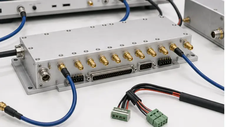
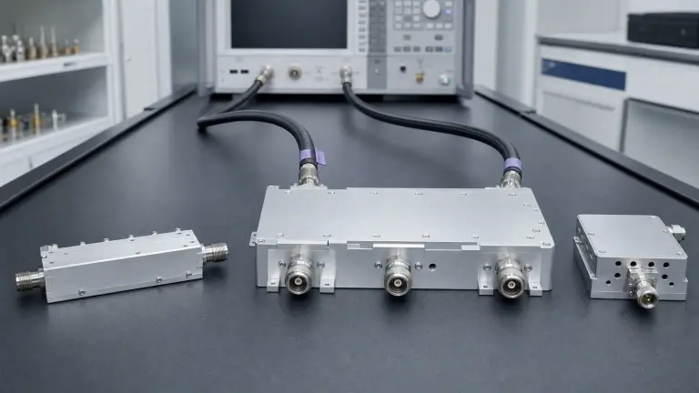
RF Component Characterization and Test Plan

Articles

FAQ

How should RF filter power handling be derated for insertion loss and temperature?

Derate RF filter power from actual dissipated heat, mismatch and field stress at the declared CW or pulsed waveform, mounting and temperature, then recheck the frequency mask at equilibrium.

Which hot-switch, cold-switch and settling-time details belong in an RF switch RFQ?

An RFQ must separate carry power from power during transition and define the command, blanking, contact or logic change, RF settling, recovery and readback sequence.

When should an electromechanical RF switch be used instead of a solid-state switch?

Electromechanical and solid-state switches occupy different loss, isolation, speed, power, size, control and lifetime boundaries; the route and switching sequence decide which is preferable.

How do insertion loss, isolation and crosstalk affect an RF switch route?

Insertion loss reduces the wanted path; isolation and crosstalk bound unwanted energy between named routes, so all three must be budgeted at the assembled matrix ports.

What is the difference between a reflective and an absorptive RF switch?

A reflective switch leaves an unselected port mismatched, while an absorptive switch presents a defined termination over stated conditions; that choice affects stability, transients and off-port power.

What is the difference between RF filter insertion loss and return loss?

Insertion loss measures transmission reduction through the intended path; return loss measures mismatch at a port under defined terminations, so both are needed.

How is duplexer isolation different from out-of-band rejection?

Out-of-band rejection describes attenuation on one path versus frequency; duplexer isolation describes leakage between named ports in a defined simultaneous operating and termination state.

When does an RF filter need a group-delay or phase-linearity specification?

Specify group-delay ripple or phase linearity when phase variation across the occupied band can distort pulses, symbols, ranging or channel-to-channel timing.

Engineering inquiry

Share your RF requirement

Share the product, operating requirements and project context. Our engineering team will route your request to the right specialist.

AttachmentsAttach drawings, BOMs, specifications or test files. Up to 5 files, 10 MB each and 25 MB total.
or drag and dropPDF, DOCX, XLSX, CSV, TXT, JPG, PNG, S1P and S2P
Typically reviewed within one business dayProject information is handled confidentially