
LCRF

Privacy preferences

Choose optional purposes independently. You can change or withdraw your choice at any time from the footer.

Strictly necessary

Required for security, session functions and storing your privacy choice.

Always active
Preferences

Remembers optional display or language settings when these features are enabled.

Analytics

Uses first-party visitor and session identifiers to measure pages, referrals and inquiry interactions.

Marketing

Allows marketing measurement or third-party advertising technologies if they are introduced in the future.

Spectrum Monitoring RF Hardware

RF and microwave hardware for observing spectrum activity, interference sources and receiver-path behavior in fixed, mobile and test environments.

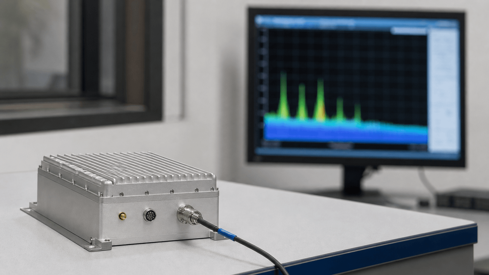
Spectrum Monitoring RF application visual

RF receive paths for spectrum monitoring

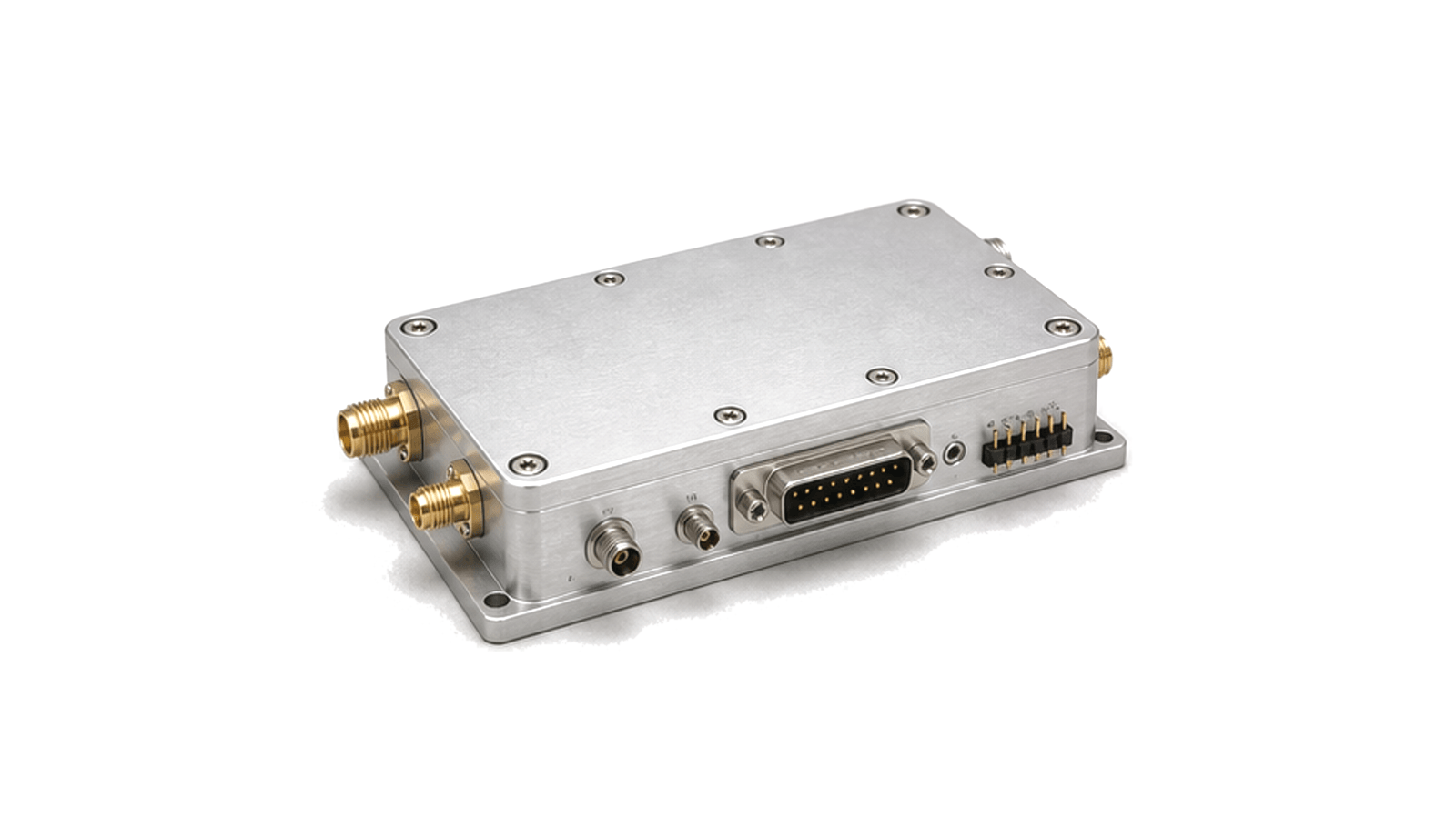
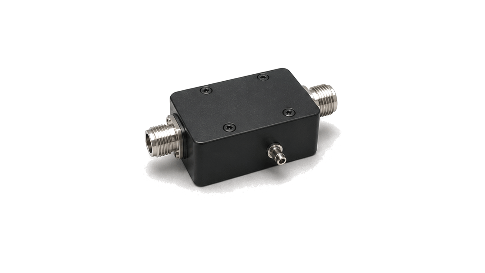
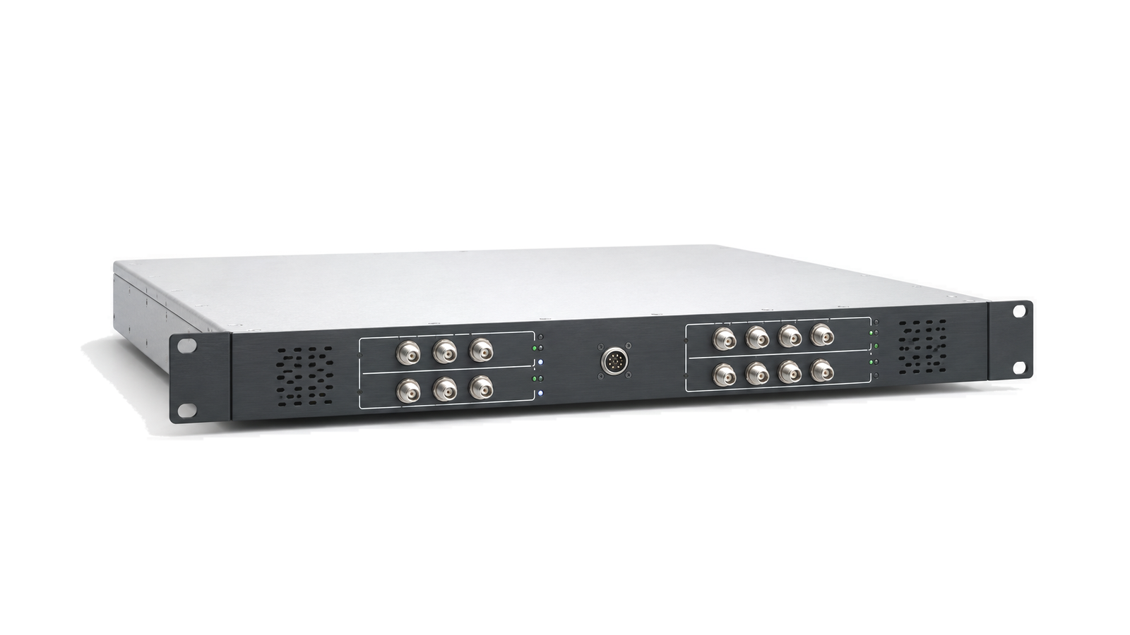
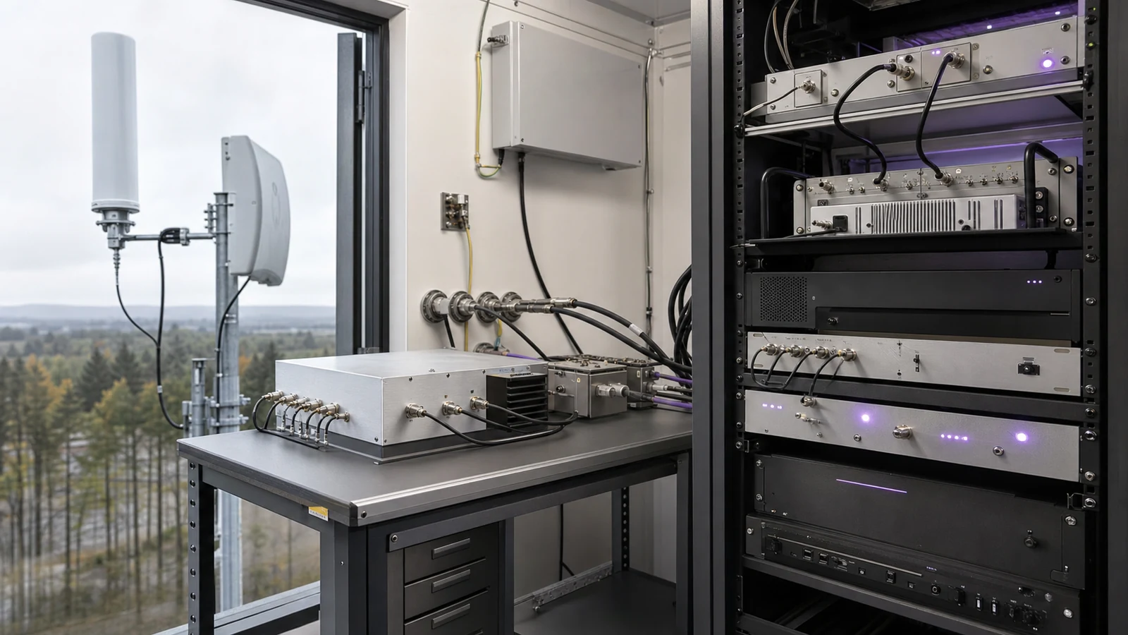
Spectrum monitoring uses RF and microwave hardware to observe signal activity across a defined frequency range. The receive path can include antennas, low-noise receiver front ends, RF detectors, frequency converters and monitoring receiver front ends.

Operating context

These systems appear in site surveys, interference investigation, perimeter RF awareness, laboratory observation and security monitoring. The hardware is usually arranged to preserve sensitivity, dynamic range and frequency coverage while keeping the path stable enough for repeatable measurements.

Engineering data

Relevant data includes frequency range, noise figure, gain distribution, input protection, conversion plan, detection threshold, instantaneous bandwidth, linearity, connector interface and calibration state.

Treat spectrum monitoring as an evidence chain

RF hardware for Spectrum Monitoring
Define the monitoring mission before choosing receiver bandwidth List the bands, channel plans, services, emission types and geographic sectors that must be observed. Separate continuous occupancy, intermittent interferers, short bursts, technical compliance checks and event capture because each needs a different relationship among instantaneous bandwidth, frequency resolution, dwel...
Spectrum Monitoring RF requirements
Define the monitoring mission before choosing receiver bandwidth List the bands, channel plans, services, emission types and geographic sectors that must be observed. Separate continuous occupancy, intermittent interferers, short bursts, technical compliance checks and event capture because each needs a different relationship among instantaneous bandwidth, frequency resolution, dwel...
Spectrum Monitoring RF architecture
Define the monitoring mission before choosing receiver bandwidth List the bands, channel plans, services, emission types and geographic sectors that must be observed. Separate continuous occupancy, intermittent interferers, short bursts, technical compliance checks and event capture because each needs a different relationship among instantaneous bandwidth, frequency resolution, dwel...
Spectrum Monitoring RF hardware selection
Define the monitoring mission before choosing receiver bandwidth List the bands, channel plans, services, emission types and geographic sectors that must be observed. Separate continuous occupancy, intermittent interferers, short bursts, technical compliance checks and event capture because each needs a different relationship among instantaneous bandwidth, frequency resolution, dwel...
Spectrum Monitoring RF testing and verification
Verify the installed chain and preserve enough evidence to repeat the result Use a conducted path to characterize gain, noise, filters, image and spurious responses, IP3 or overload and amplitude accuracy; then repeat representative checks through the installed antenna path with known site signals or a controlled field source....

Spectrum Monitoring Receiver Front Ends: Dynamic Range, Scan Coverage and Verification

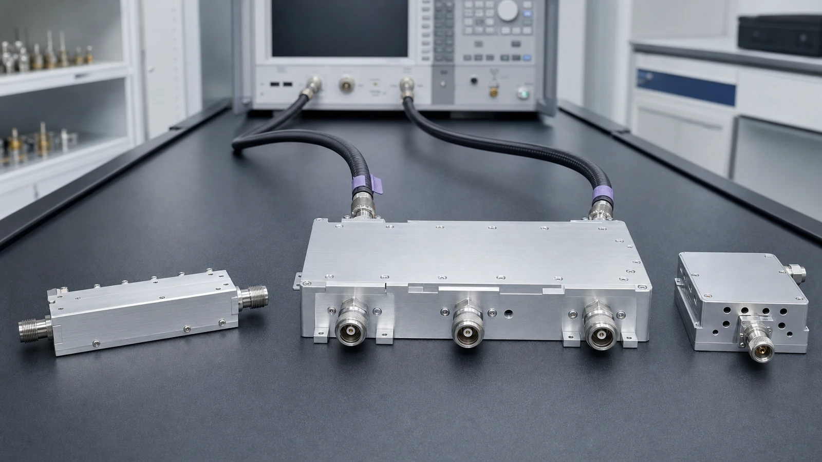
Specify a spectrum-monitoring receiver from antenna coverage to recorded evidence by balancing weak-signal sensitivity, strong-signal tolerance, preselection, instantaneous bandwidth, RBW, dwell, revisit time, thresholds, timing and calibration.
Spectrum Monitoring Receiver Front-End Specification

Articles

FAQ

How should preselection, blocker tolerance and overload limits be specified for a monitoring receiver?

Specify each band state by preselector rejection, insertion loss, gain or attenuation, noise figure, IP3 or compression, full-scale margin, overload indication and recovery under a simultaneous weak signal.

Which recording, timing and calibration interfaces belong in a spectrum-monitoring system specification?

Specify retained data, trigger and buffer behavior, complete RF metadata, time and frequency references, amplitude corrections, calibration injection, uncertainty and change-controlled export formats.

How should the simultaneous signal environment be specified for a spectrum-monitoring receiver?

Define weak signals and every simultaneous strong emitter by frequency, waveform, bandwidth, level, duty cycle, timing, antenna or conducted coupling plane and required observation outcome.

How are RBW, dwell time and scan coverage related in spectrum monitoring?

Coverage is bounded by monitored span, instantaneous bandwidth, step or FFT-bin spacing, RBW, settling and processing overhead, dwell per segment, revisit time and the duration of the event of interest.

When does an RF filter need a group-delay or phase-linearity specification?

Specify group-delay ripple or phase linearity when phase variation across the occupied band can distort pulses, symbols, ranging or channel-to-channel timing.

How is duplexer isolation different from out-of-band rejection?

Out-of-band rejection describes attenuation on one path versus frequency; duplexer isolation describes leakage between named ports in a defined simultaneous operating and termination state.

What is the difference between RF filter insertion loss and return loss?

Insertion loss measures transmission reduction through the intended path; return loss measures mismatch at a port under defined terminations, so both are needed.

How should RF filter power handling be derated for insertion loss and temperature?

Derate RF filter power from actual dissipated heat, mismatch and field stress at the declared CW or pulsed waveform, mounting and temperature, then recheck the frequency mask at equilibrium.

Engineering inquiry

Share your RF requirement

Share the product, operating requirements and project context. Our engineering team will route your request to the right specialist.

AttachmentsAttach drawings, BOMs, specifications or test files. Up to 5 files, 10 MB each and 25 MB total.
or drag and dropPDF, DOCX, XLSX, CSV, TXT, JPG, PNG, S1P and S2P
Typically reviewed within one business dayProject information is handled confidentially