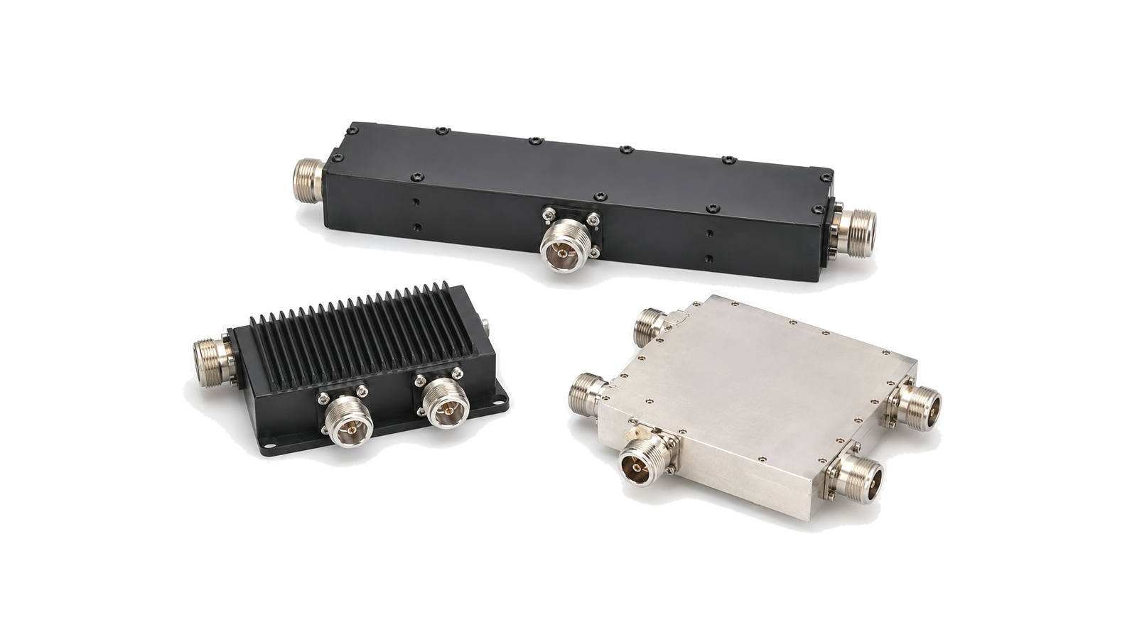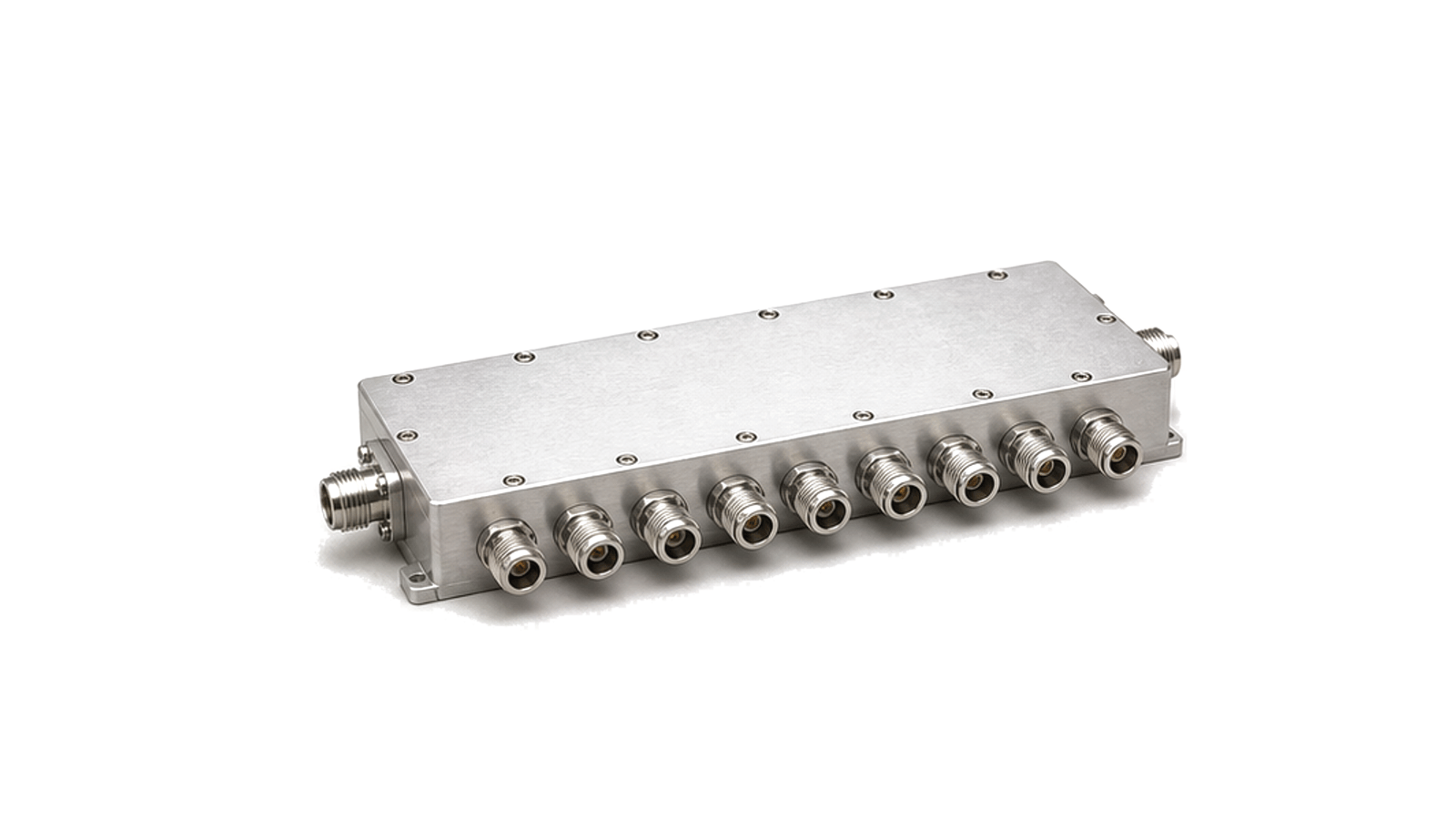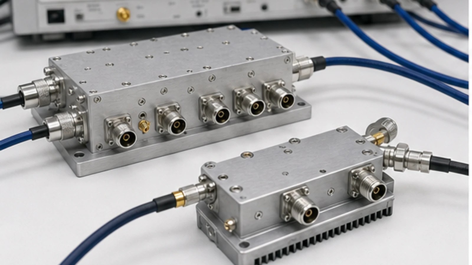
Start with the port sketch
Draw the driven port, required outputs, signal arrows and every unused-port termination before opening a data sheet. The drawing decides the device: a divider creates controlled branches, a combiner accepts coherent sources, and a directional coupler samples one travelling-wave direction while preserving the main path. Only then compare full-band loss, balance, isolation or directivity, match, peak and average power, mismatch behavior and environmental limits at identical reference planes. If the vendor's port state, power definition or test condition cannot be reconciled with the sketch, the part is not comparable.
Decision matrix: divider, combiner or coupler?
The first decision is functional. A weighted score is useful only after the architecture, port count, phase relationship and sampling ratio are fixed.
| Required function | Preferred starting family | Evidence required | Reject when |
|---|---|---|---|
| Equal outputs from one source | 0-degree power divider or Wilkinson network | Port count, theoretical split, excess loss, amplitude/phase balance, output isolation | Balance or isolation is not demonstrated over the complete band and temperature range |
| Combine coherent sources | Reciprocal divider/combiner, hybrid or engineered combining network | Input amplitude/phase tolerance, isolation, load behavior, per-port and combined power | The source paths cannot remain aligned or a failed path can damage another source |
| Sample forward or reflected power | Directional or bidirectional coupler | Coupling factor, coupling flatness, directivity, main-line loss, power and orientation | Directivity is too low to separate the desired wave from leakage |
| Create quadrature or differential paths | 90-degree or 180-degree hybrid | Phase balance, amplitude balance, isolation, termination and bandwidth | The downstream calibration cannot absorb phase and amplitude error |
| Very broad coverage including low frequency | Resistive divider when its loss and isolation are acceptable | Total loss, isolation, thermal dissipation and noise-budget effect | Added loss or branch coupling breaks the system budget |

Define signal direction and reference planes first
Every loss, match and isolation requirement must name the driven port, observed port and termination state of the remaining ports. A three-port or four-port network changes behavior when an unused port is open, shorted or terminated incorrectly. Define the system impedance, connector reference planes, adapter and cable inclusion, source and load mismatch, and whether calibration removes fixture loss.
For a divider, record the common input and each output. For combining, reverse the signal direction only after confirming the device is specified for reciprocal use and the sources can tolerate residual coupling. For a directional coupler, identify input, output, coupled and isolated ports plus the arrow or orientation used for forward and reverse sampling.
Separate theoretical split loss from excess insertion loss
An ideal equal N-way divider has an unavoidable split loss of 10 log10(N) dB per output before conductor, dielectric, transformer and mismatch loss are added. Data sheets may state total insertion loss or only excess loss, so the definition must be checked before two products are compared.
| Ways | Ideal power per output | Ideal split loss |
|---|---|---|
| 2 | 50% | 3.01 dB |
| 3 | 33.3% | 4.77 dB |
| 4 | 25% | 6.02 dB |
| 8 | 12.5% | 9.03 dB |
Worked two-way divider example
A 2-way divider is measured at 3.45 dB total loss from the input to output 1 and 3.62 dB to output 2 at the project frequency. The ideal split is 3.01 dB. Excess losses are therefore 0.44 dB and 0.61 dB. The output amplitude imbalance is 0.17 dB. With +30 dBm at the common input and no mismatch correction, the approximate output powers are +26.55 dBm and +26.38 dBm. This calculation does not prove phase balance, isolation, return loss or power survivability; those remain separate acceptance items.
How balance, isolation and directivity change the system
Amplitude and phase balance determine how evenly parallel paths are driven and how efficiently coherent signals combine. Small branch errors can become beam, cancellation, calibration or power-sharing errors in arrays and balanced architectures. Specify balance over the complete frequency and temperature range, not only at the center frequency.
Divider isolation describes unwanted coupling between output branches. Low isolation allows the load or reflection on one branch to modulate another branch. In a combiner, residual input-to-input coupling can expose one source to another source's output and can turn phase or amplitude error into internal dissipation.
Coupler directivity describes how well the coupled port distinguishes the intended travelling wave from leakage associated with the opposite direction. When quantities are expressed in positive dB magnitudes, a common relationship is directivity = isolation - coupling - main-line insertion loss. Confirm the manufacturer's sign convention and port definition before applying the equation.
Power handling is a multi-port condition
A combiner cannot be rated from combined output power alone. Record average and peak power at each input, phase and amplitude mismatch, waveform duty cycle, crest factor, temperature, load VSWR and the allowed fault state. If two nominally equal inputs drift out of phase, the desired output falls and power can be dissipated in an isolation resistor, termination or lossy structure. A headline matched-load rating does not establish safe behavior under that imbalance.
For couplers, separate main-line power from power delivered to the coupled port and from the termination rating at the isolated port. For pulsed service, include pulse width, repetition rate and peak envelope power. For modulated signals, include average power, crest factor and any linearity or EVM consequence of heating and mismatch.
Verification plan for a multi-port passive network
- Calibrate to named connector or fixture reference planes. Record adapters, cables and de-embedding.
- Terminate every unused port in the specified impedance. Use terminations with adequate frequency and power ratings.
- Measure all relevant S-parameters. Include input/output return loss, path transmission and inter-port isolation in both required directions.
- Calculate amplitude and phase balance from the same sweep. Retain worst-case values over frequency and temperature.
- For couplers, verify coupling flatness and directivity. Keep port orientation and sign convention explicit.
- Repeat at representative power. Check heating, compression, drift, connector temperature and termination load.
- Exercise mismatch and fault cases when the application requires them. Define VSWR magnitude, phase coverage, duration and pass/fail behavior.
- Separate qualification from production acceptance. A full characterization may justify a smaller per-unit test set, but the correlation must be documented.
Common selection failures
- Comparing a total path loss from one supplier with excess loss from another.
- Using a directional coupler where equal low-loss outputs are required.
- Combining sources without defining phase, amplitude and fault-state tolerance.
- Leaving unused ports unterminated during measurement or system operation.
- Specifying isolation but omitting port match, which can limit practical isolation and directivity.
- Checking balance only at center frequency while the system uses a wide instantaneous band.
- Applying a CW matched-load power rating to high-crest-factor, pulsed or mismatched service.
- Ignoring the power dissipated by isolation resistors or terminations during imbalance.
Minimum RFQ and acceptance checklist
- Required function: divide, combine, sample, quadrature, differential or distribution network
- Frequency band, guard bands and temperature range
- System impedance, port count, connector gender and reference planes
- Split or coupling ratio and allowed flatness
- Total path loss and whether excess loss must be stated separately
- Amplitude and phase balance by frequency and temperature
- Output/input isolation, coupler directivity and port return loss
- Average, peak and pulse power at every port
- Load VSWR, phase coverage, fault duration and survival behavior
- Outline, mounting, cooling, mass and environmental limits
- Qualification sweeps, per-unit acceptance limits and required data format