
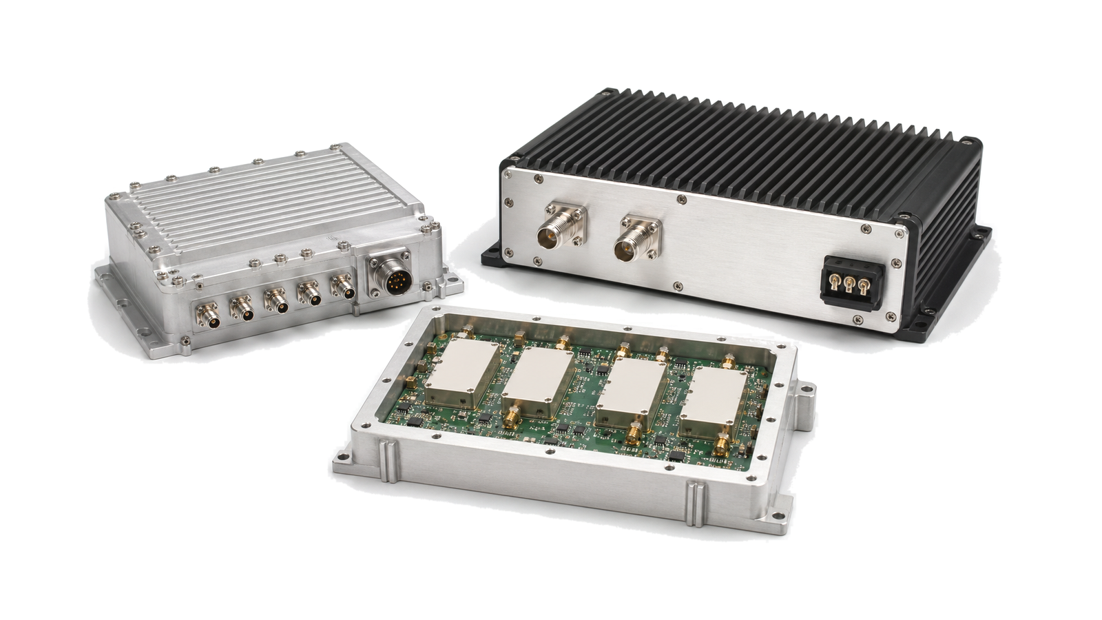
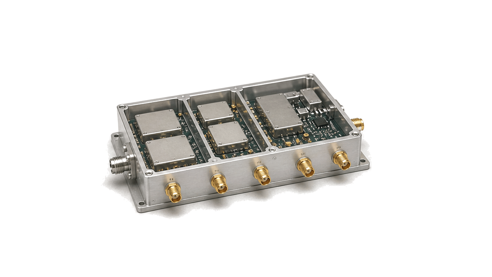
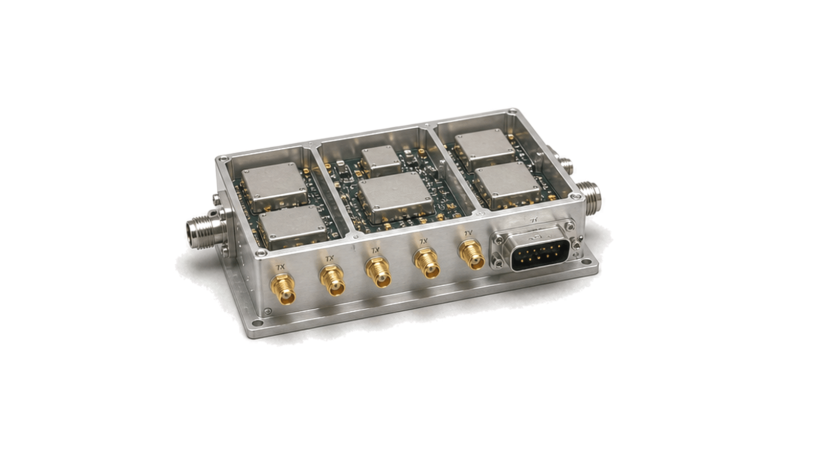
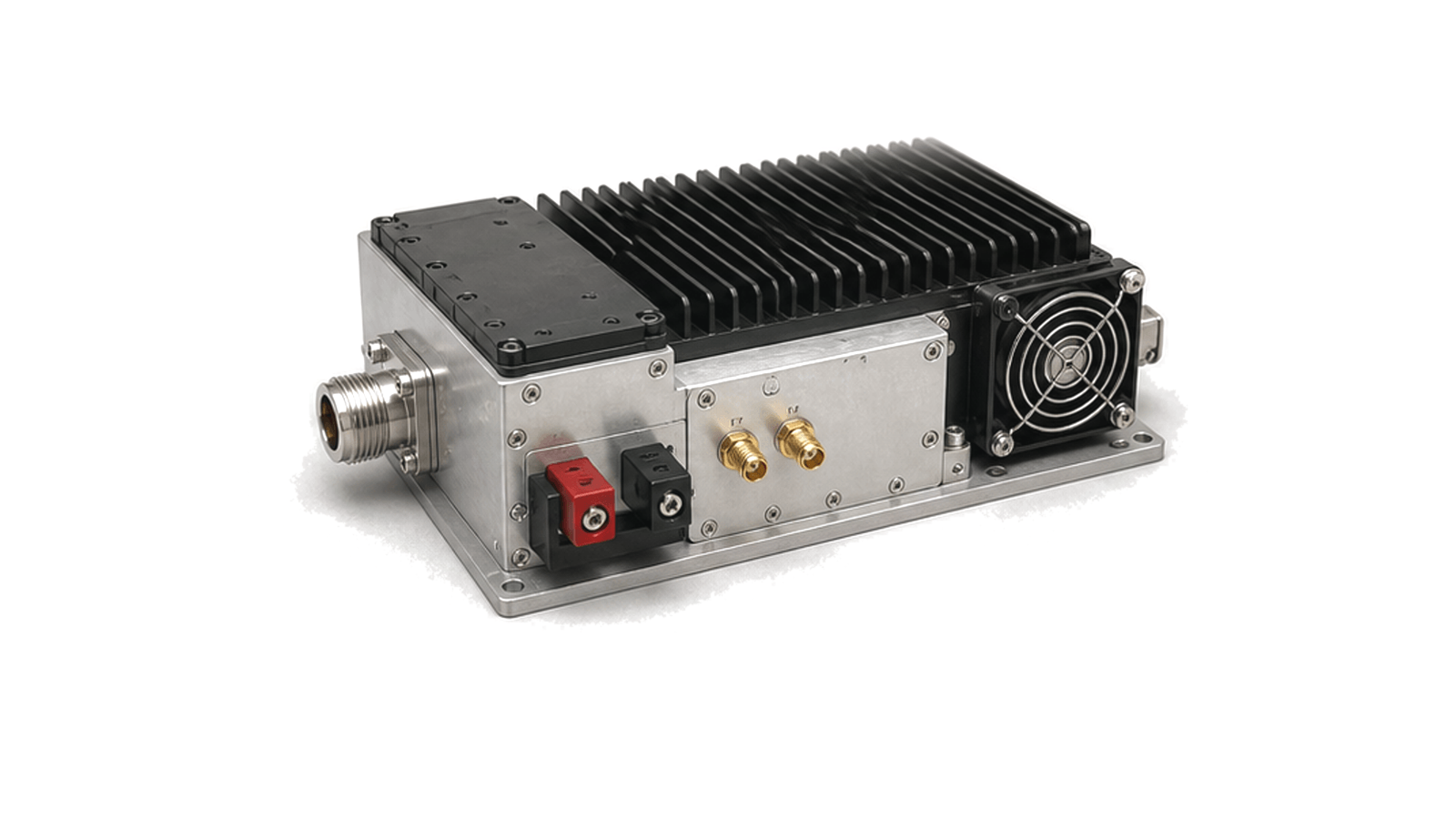
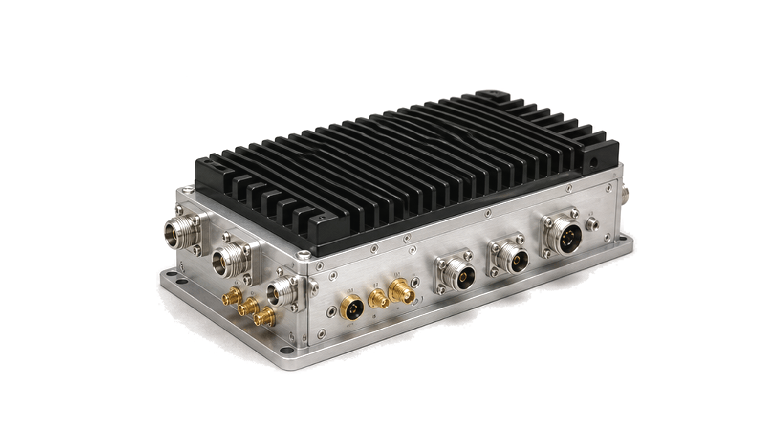
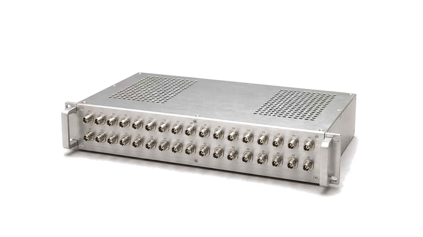
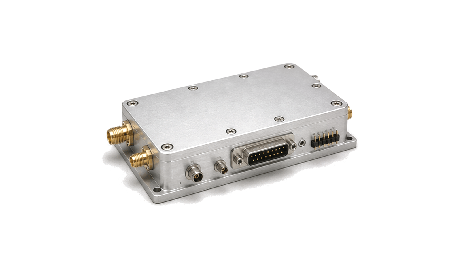
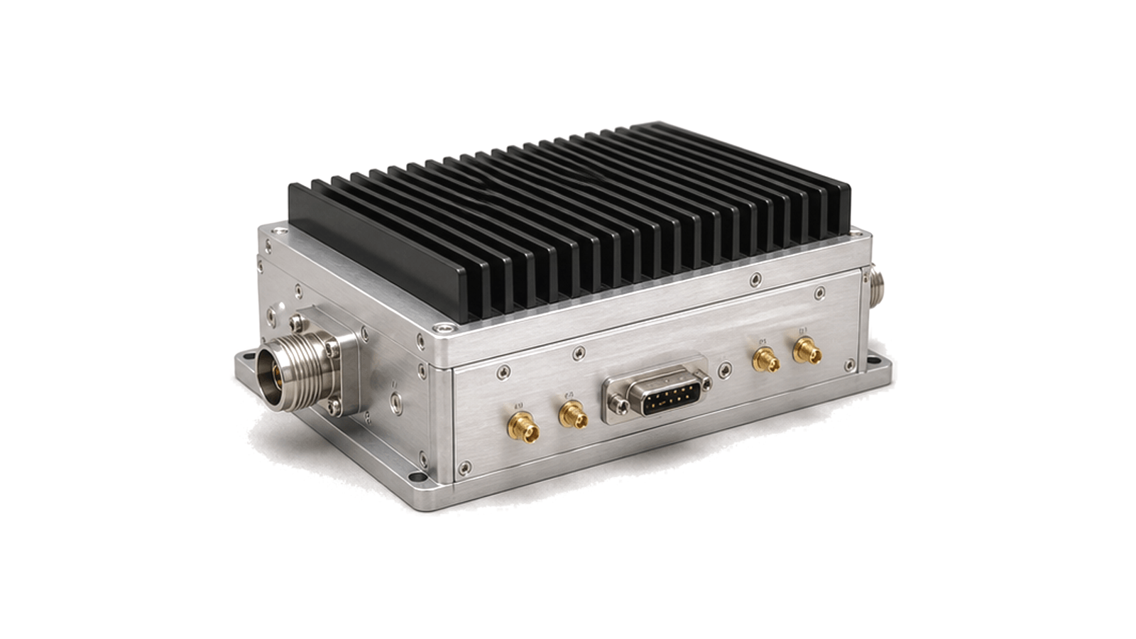
What is an RF front-end subsystem?
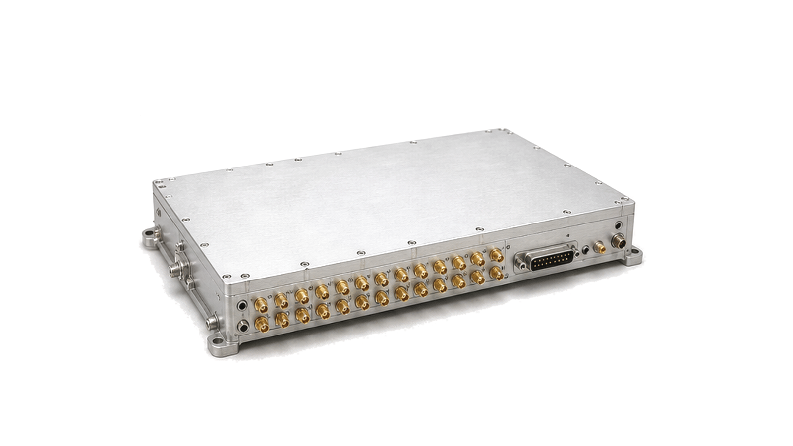
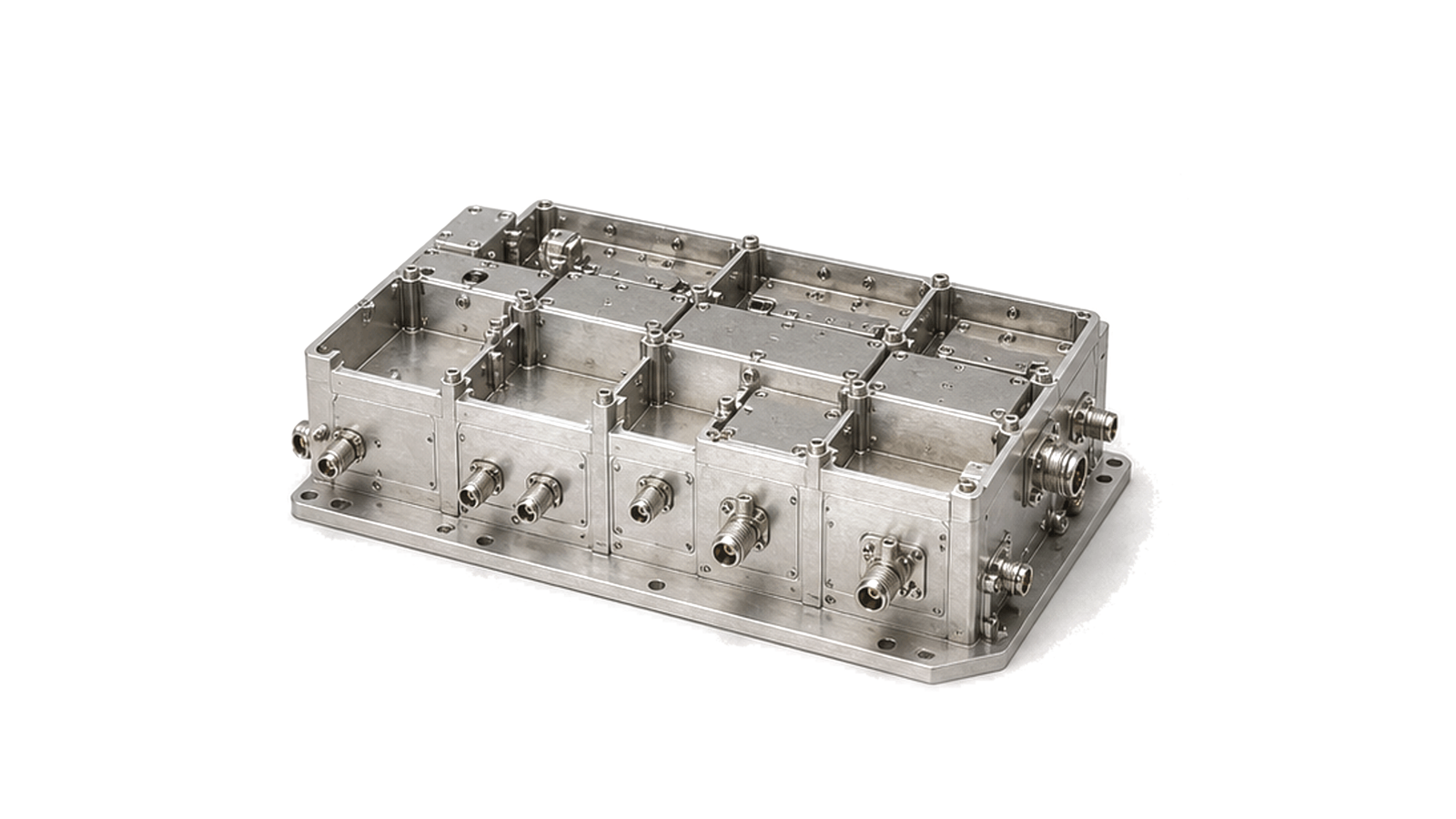
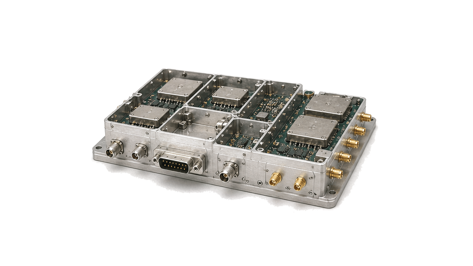
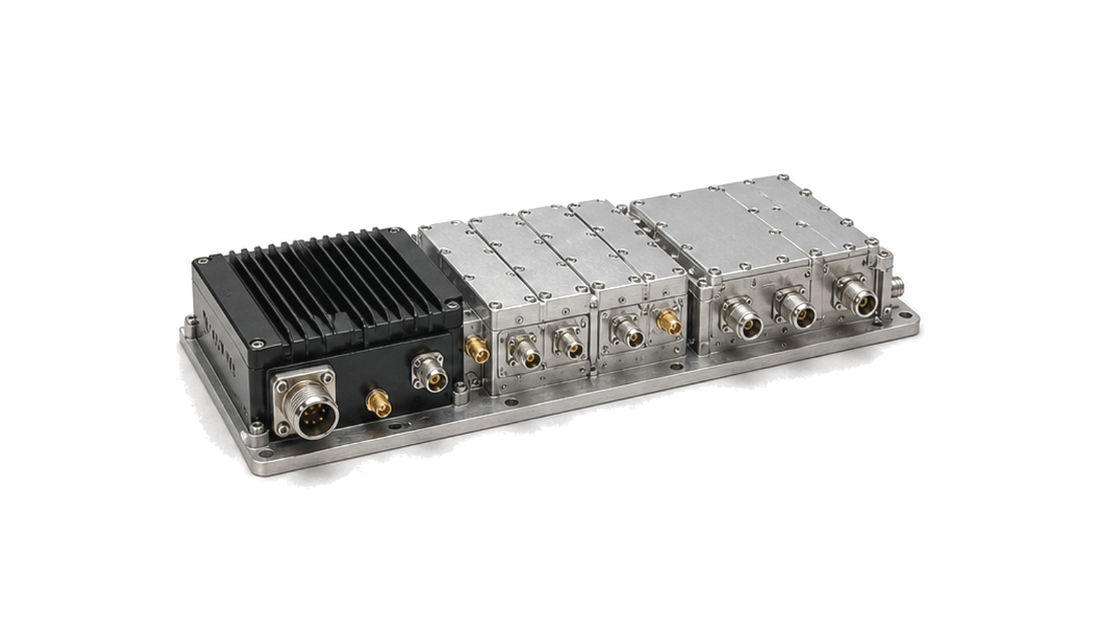
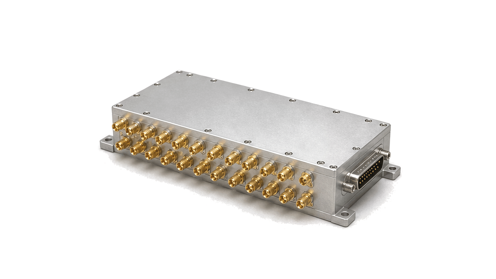
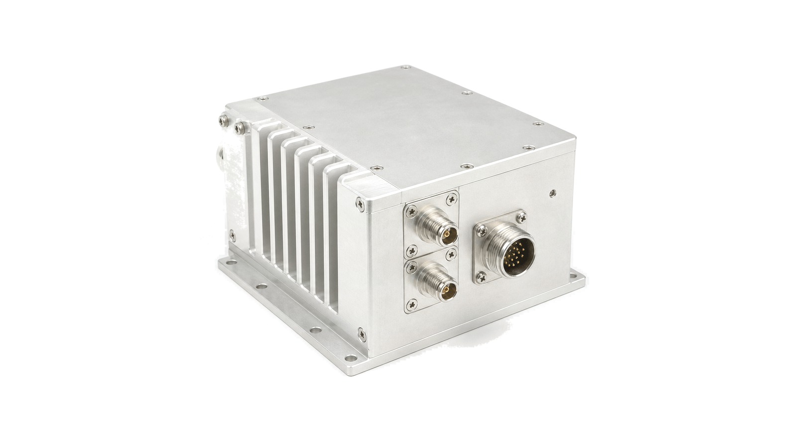
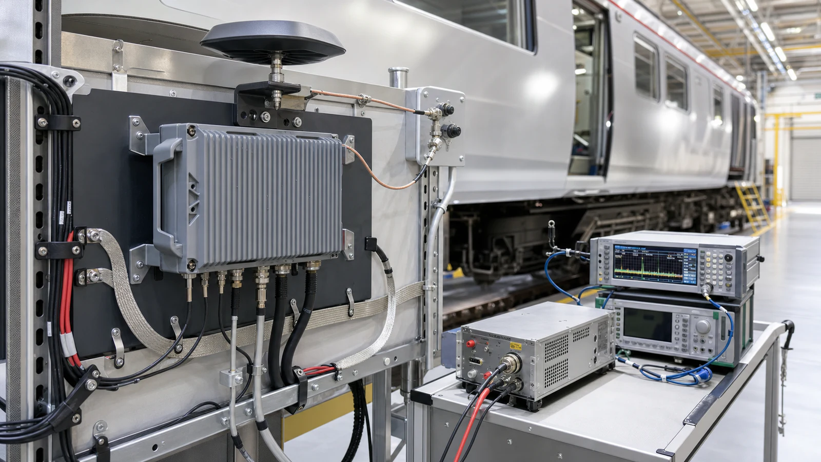
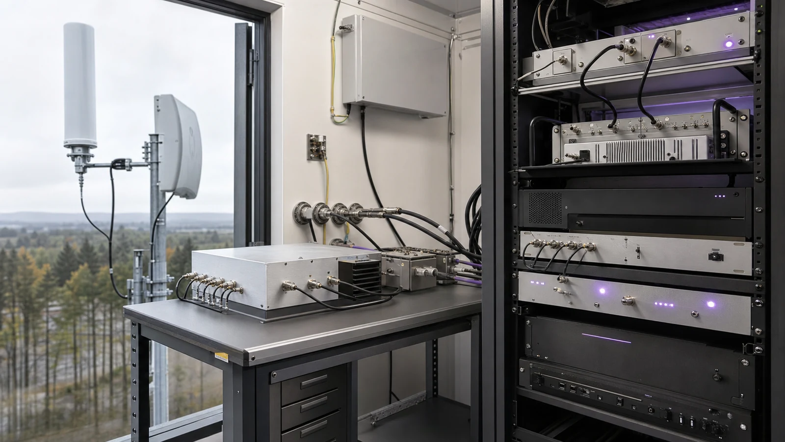
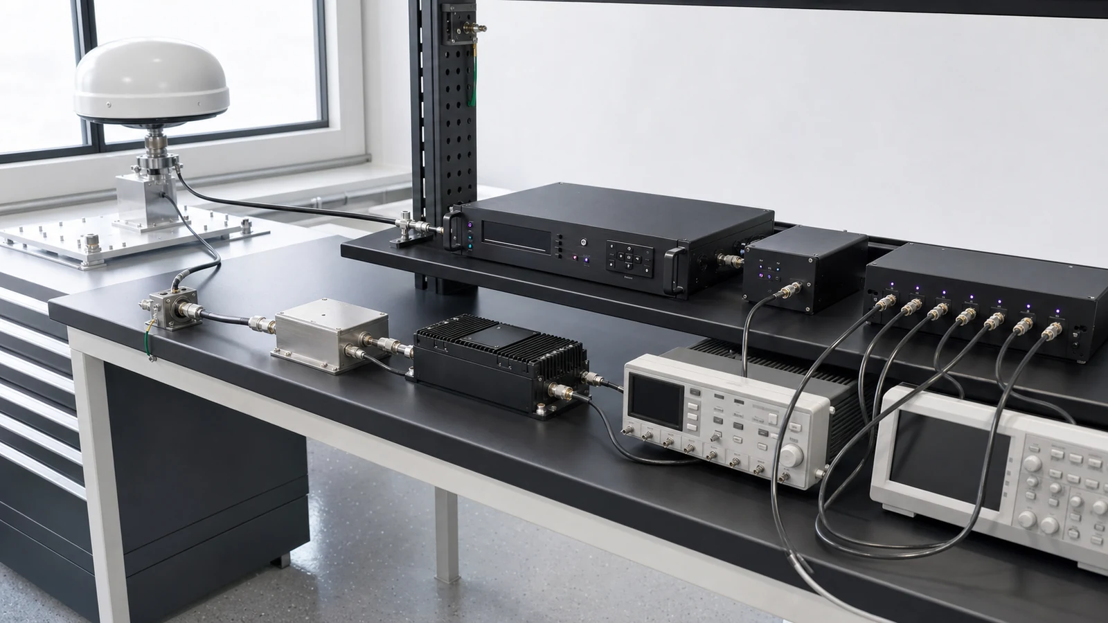
An RF front-end subsystem is the controlled signal-path assembly between an antenna or RF port and an IF, baseband or digital interface, combining the functions needed to receive, transmit or both. It can include filters, limiters, switches, LNAs, gain control, mixers, local-oscillator distribution, power stages, couplers, detectors and embedded control. Its value is the verified behavior of the complete operating modes, not the sum of individual component data sheets.
Decisions this category must close
- RF front-end module and subsystem supplier: checks whether a source can freeze interfaces, states, evidence and change control before quotation
- RF front-end module and subsystem manufacturer: separates production repeatability and configuration control from a successful prototype result
- RF front-end module and subsystem technical specifications: compares gain, noise, blocking, linearity, output, isolation, control and thermal limits at common reference planes
- RF front-end module and subsystem selection guide: matches receiver, transmit/receive, conversion or multi-function architecture to the required operating states
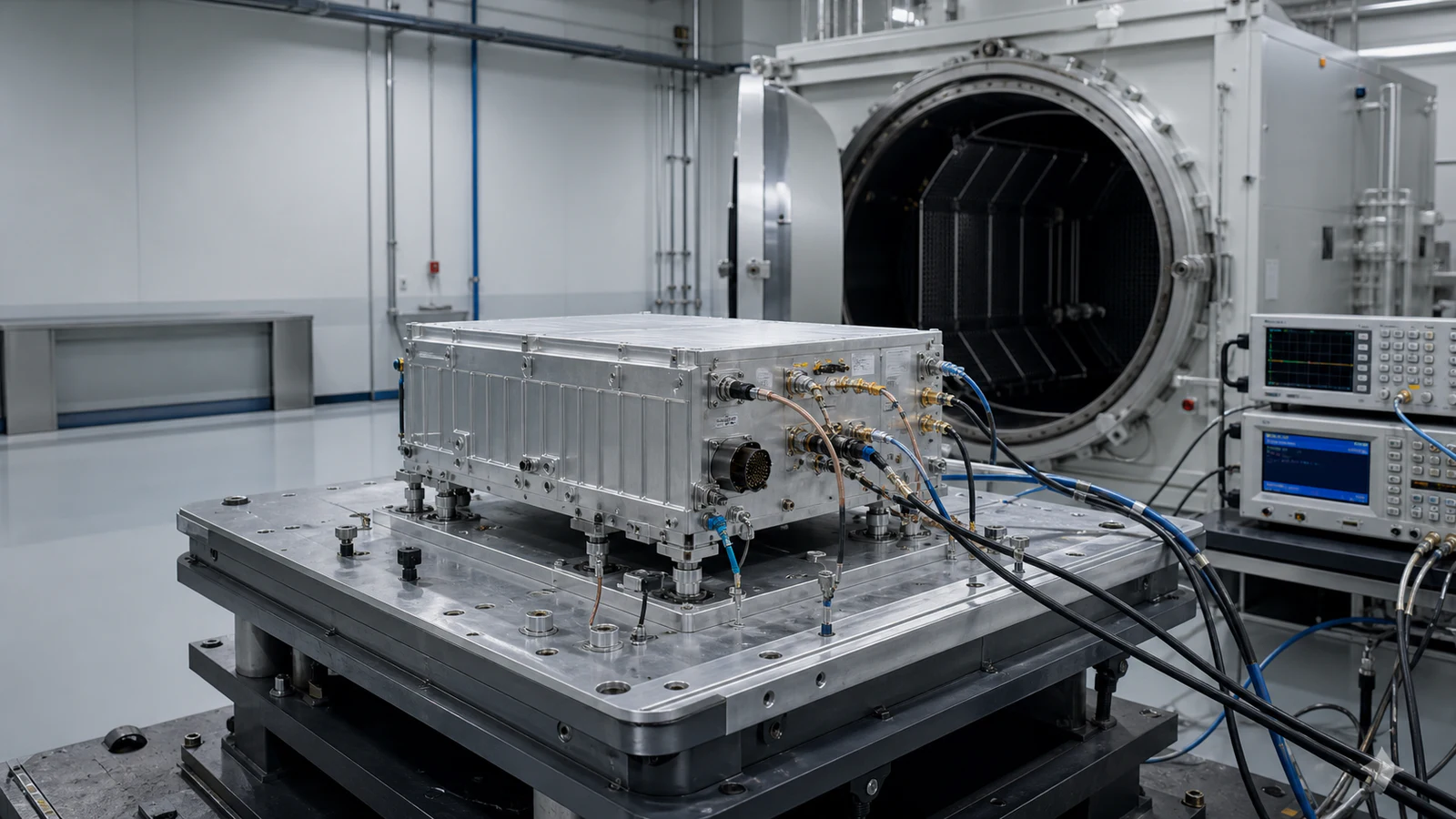
- RF front-end module and subsystem test and verification: defines port-to-port acceptance across frequency, temperature, supply, switching, mismatch and fault conditions
Qualify the source before comparing headline specifications
A credible source should provide an interface-control drawing, operating-state table, named RF reference planes, configuration and revision identity, calibrated test coverage, thermal evidence, nonconformance control and change notification. Reject a proposal that substitutes component data for assembled performance, omits prohibited switching states or cannot tie a result to the delivered hardware and software revision.
Architecture selection and rejection matrix
| Architecture path | Choose when | Required evidence | Reject when |
|---|---|---|---|
| Receiver front end | Sensitivity and blocker coexistence dominate | Cascaded gain and noise figure, gain states, IIP3, reciprocal-mixing and preselector-loss results | Only small-signal noise figure is shown |
| Transmit/receive front end | One antenna or duplex path serves both directions | Output power, modulation quality, isolation, switching transient, mismatch and recovery data | T/R leakage or transition states are undefined |
| Frequency-converting front end | The interface moves between RF and IF or direct-sampling bands | LO phase noise, image and spur map, conversion gain, reference and clock conditions | The spur plan excludes blockers or alternate LO states |
| Integrated multi-function subsystem | Routing, calibration, control and heat are shared across modes | State table, reference-plane definition, interface control and port-to-port acceptance by temperature and fault | A stack of component data sheets replaces subsystem evidence |
Freeze interfaces, paths and reference planes first
Define RF and IF bands, instantaneous bandwidth, impedance, antenna ports, duplex or T/R architecture, conversion plan, clock and LO inputs, control protocol, power rails and mechanical envelope. Every receive, transmit, bypass, calibration, termination and prohibited route should have an explicit state and safe transition. Reference planes must be consistent across gain, noise, power and phase data.
Close receive and transmit budgets in the same assembly
Receiver approval requires cascaded gain, noise figure, sensitivity, IIP3, compression, blocker tolerance, image rejection and spurious response. Transmit approval requires output power, gain, compression, harmonics, intermodulation, spectral or modulation quality and load mismatch behavior. Shared filters, switches and duplexers create isolation and leakage paths that neither one-way budget reveals alone.
Verify control, calibration, protection and heat by operating mode
Specify switching time, settling, phase continuity, gain-state repeatability, telemetry, fault reporting, interlocks, power sequencing and recovery. Calibration must state reference plane, coefficients, storage and temperature update. Thermal design should cover simultaneous channels, duty cycle and blocked airflow. Test matrices need normal paths, boundary states, blockers, switching transients and fault injection.
- RF, IF and digital interfaces, bands, bandwidth and impedance
- receive, transmit, bypass, calibration and safe-state routing
- gain, noise figure, blocker, IIP3, compression and spurious map
- output power, modulation quality, harmonics, mismatch and isolation
- control protocol, switching, telemetry, interlocks and recovery
- calibration planes, thermal duty, mechanical envelope and acceptance matrix
Acceptance boundary
Approve the subsystem from port-to-port measurements in every required state, including blocker, switching, temperature, supply and fault conditions. Component-level compliance does not prove receiver sensitivity, transmit cleanliness or isolation of the integrated front end.