
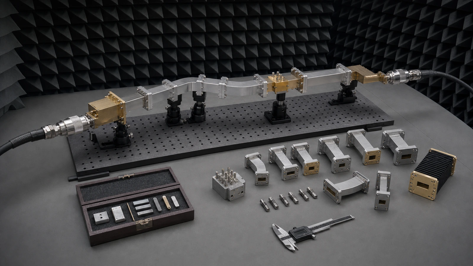
How to Specify an RF Coaxial Cable Assembly: Insertion Loss, VSWR, Power, Phase Stability and Bend Life
Specify an RF coaxial cable assembly as one controlled two-port configuration. Freeze both connector interfaces, gender and orientation, assembly length and tolerance, routing, minimum static and dynamic bend radius, continuous frequency band, reference impedance, insertion-loss and return-loss limits, average and peak power, phase or delay stability, shielding, temperature and environment. Define the calibrated reference planes, connector torque, preconditioning, flexure and thermal sequence, uncertainty, pass/fail limits and retained Touchstone or tabular data. A cable-series attenuation curve or connector frequency rating alone cannot qualify the finished assembly. Engineering selection for coaxial cable assemblies, semi-rigid interconnects, connectors, adapters and related conducted RF paths, bounded by frequency, impedance, insertion loss, reflection, power, phase stability, routing, environment and acceptance evidence. A field-ready method for specifying RF and microwave coaxial cable assemblies by topology, calibrated reference planes, insertion loss, return loss, power, phase and amplitude stability, delay, shielding, bend limits, connector control, environment and acceptance evidence.
Commercial and engineering decisions covered
- RF Transmission & Interconnect supplier: select the conducted RF path and evidence boundary
- RF Transmission & Interconnect manufacturer: freeze electrical mechanical environmental and acceptance limits
- RF Transmission & Interconnect technical specifications: verify complete assembly transmission at declared planes
- RF Transmission & Interconnect selection guide: freeze route connector and mechanical life
- RF Transmission & Interconnect test and verification: design a traceable acceptance sequence
Define continuous frequency coverage and both reference planes
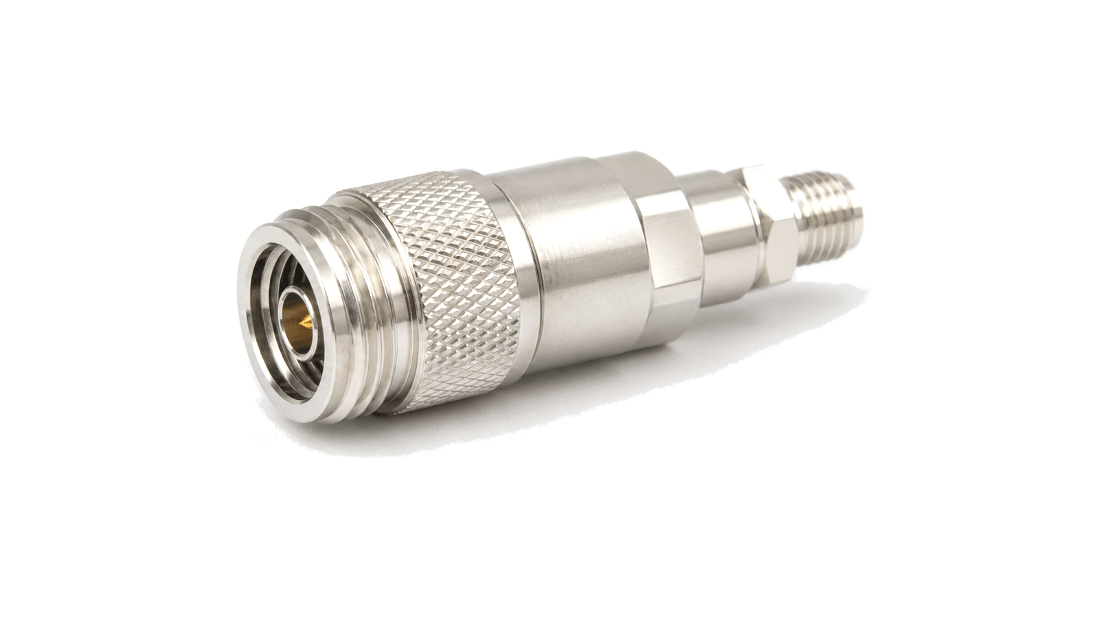
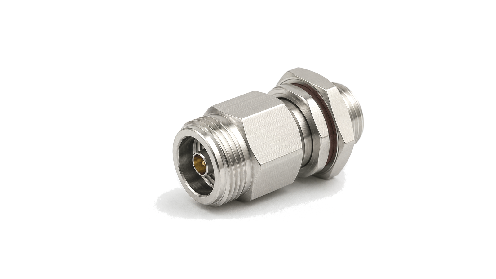
Use continuous operating and verification bands rather than one center frequency or the connector's headline rating. Name the reference impedance and both calibrated planes: normally the mating interfaces, but sometimes a fixture or launch plane when the assembly is integrated. State whether adapters, torque devices, right-angle transitions or bulkhead feedthroughs are inside the delivered boundary. Reference-plane ambiguity creates apparently conflicting data. A connector pair, adapter or fixture can add loss, reflection and delay, and de-embedding can move the reported result. Preserve the calibration method, port extension or de-embedding file and exact assembly orientation so design, supplier and acceptance laboratories are comparing the same network.
Keep transmission loss and port match as separate limits
Insertion loss is derived from forward transmission, while return loss or VSWR describes reflection at each port. A low-loss cable can still have a poor connector transition, and a well-matched assembly can still dissipate too much power over a long route. Specify maximum insertion loss across the full band and separate input and output return-loss limits when the two ends or installation environments differ. Avoid approving a smooth typical curve without production tolerance. Set frequency resolution, smoothing rules, temperature states and whether limits are absolute or relative to a baseline. Retain complex S-parameters where phase, time-domain gating, de-embedding or cascade analysis matters; scalar screenshots cannot support those operations.
Check power, voltage, heating, shielding and unwanted products
State average and peak power, waveform, duty cycle, crest factor, mismatch state and fault duration. Power capability can be limited by conductor heating, dielectric loss, connector contact resistance, peak voltage, altitude, contamination or a small local discontinuity. A connector series power statement does not automatically apply to a long cable assembly at the highest operating frequency and temperature. Where receiver protection or multi-carrier purity matters, specify shielding effectiveness, leakage, passive intermodulation or connector cleanliness with a usable test method. PIM is an assembly and handling problem as much as a material property: contact condition, torque, plating, contamination and mechanical stress can dominate. Keep those requirements separate from ordinary S-parameter acceptance.
Specify phase, electrical length and delay stability by cause
Absolute phase, phase matching, group delay and time delay answer different system questions. A phased array may care about channel-to-channel phase over frequency and temperature; a timing path may care about delay; a laboratory cable may care about change after movement. State the baseline, frequency points, comparison channels and whether the limit is total variation, peak-to-peak change or repeatability after returning to a defined position. Separate flexure-induced change from temperature-induced change. Define bend radius, bend angle, movement plane, cycle count, rate and dwell, then define thermal range, ramp, soak and measurement state. Without the test geometry, a phase-stability number cannot be reproduced or compared.
Control connector, bend, strain relief and routing details
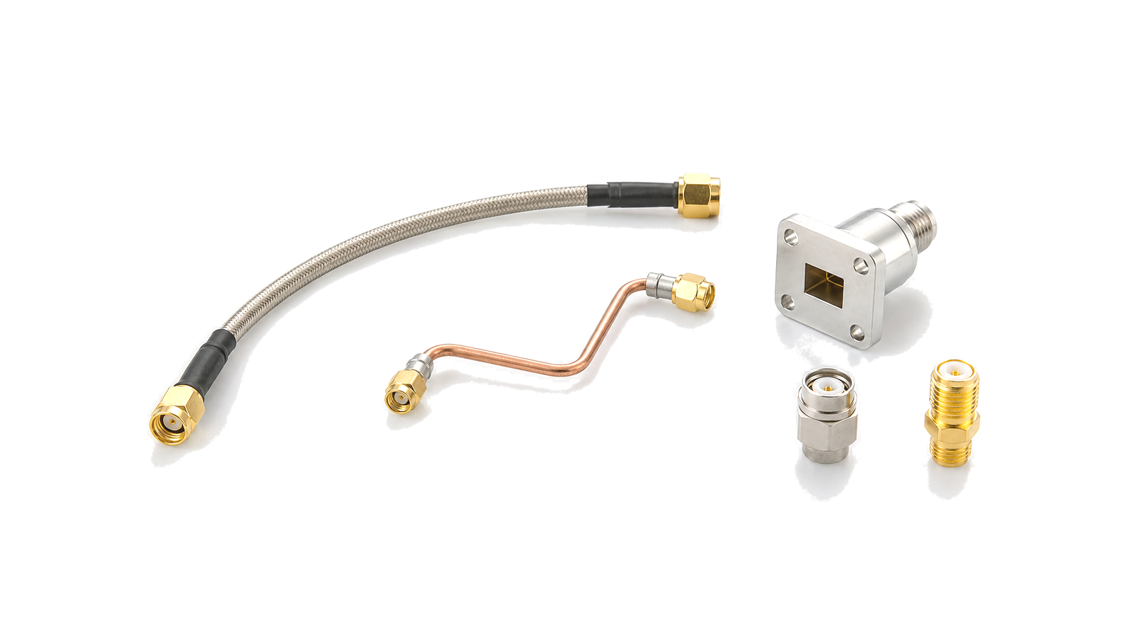
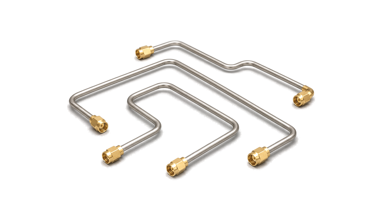
Specify connector series, precision grade where relevant, gender, orientation, plating, interface standard, mating torque, coupling-nut access and allowable mating cycles. Freeze overall length and the reference points used to measure it. For angled connectors, define clocking. For semi-rigid assemblies, supply a controlled drawing with centerline dimensions, bend radii, straight lengths and tolerances. Distinguish minimum static bend radius from dynamic bend radius and do not bend at the connector termination. Define strain relief, clamp spacing, unsupported mass, torsion, crush load and installation keep-outs. A cable that passes on a straight bench can fail after a tight route transfers bending moment into the connector or changes the dielectric geometry.
Translate the platform environment into a repeatable stress sequence
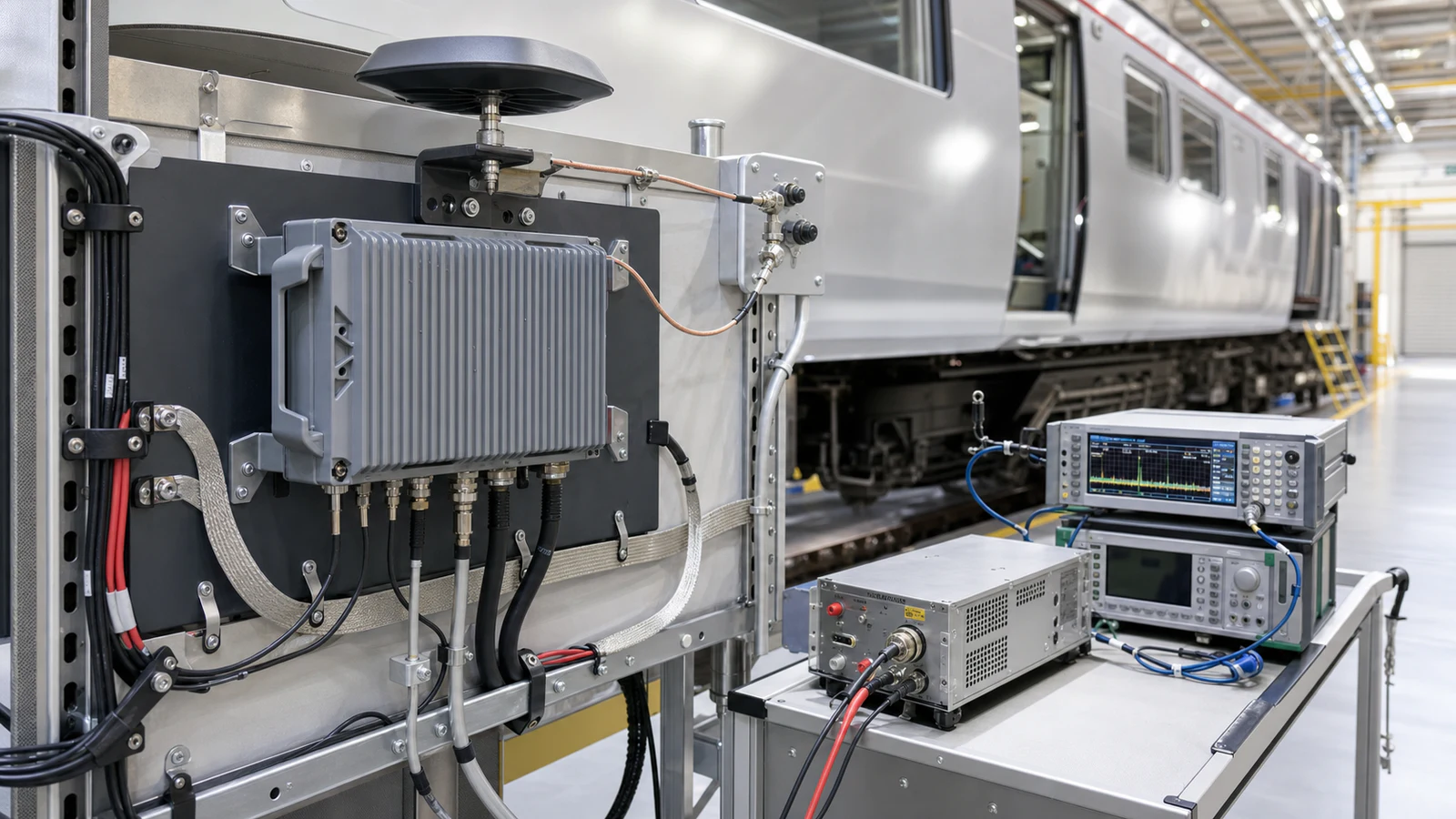
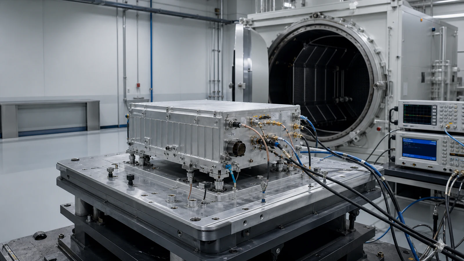
List operating and storage temperature, altitude or pressure, humidity, salt or chemical exposure, ingress, vibration, shock, radiation and flammability where applicable. Define whether RF measurements occur during exposure, at stabilized temperature or after recovery. Separate survival from retained performance: an assembly can remain electrically continuous while insertion loss, match or phase has moved outside the system budget. For flex life, define the actual movement envelope rather than a generic cycle count. Include bend radius, travel, torsion, speed, dwell, connector restraint and inspection interval. Acceptance should compare the post-stress network against both absolute limits and its own serialized baseline so gradual degradation is visible.
Design calibration, repeatability and evidence before the RFQ
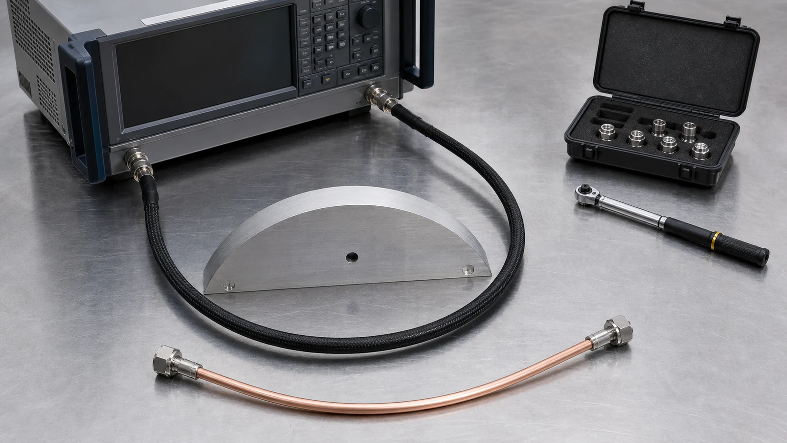
Use a VNA calibration appropriate to connector type, frequency and uncertainty. Stabilize and support test cables, inspect and clean interfaces, apply controlled torque and record adapter use. Run connector-remate and fixture-repeatability checks separately from unit repeatability; otherwise laboratory variation can be mistaken for cable instability or can hide a weak assembly. Retain native complex data, calibration identity, frequency grid, power level, IF bandwidth where relevant, temperature, routing state, serial number, drawing revision, connector history and deviations. A PDF curve may support review, but it is not a substitute for machine-readable data when the assembly will be cascaded, matched, gated or compared over service life.
Interconnect assembly selection and acceptance matrix
| Decision boundary | Requirement to freeze | Do not accept |
|---|---|---|
| Assembly topology | Use, route, movement, matched-set role and both endpoints | A cable series is proposed without the installed configuration |
| Frequency and planes | Continuous bands, impedance and calibrated plane at each end | Only center frequency or connector rating is provided |
| Transmission and match | Full-band insertion loss plus S11 and S22 limits | One typical attenuation value substitutes for assembly data |
| Power and shielding | Waveform, average/peak power, mismatch, heating, leakage or PIM | A connector headline rating is applied to the whole path |
| Phase and delay | Metric, baseline, frequency, temperature and movement method | A stability number has no test geometry |
| Mechanical configuration | Connector, torque, length, clocking, bend radius and support | The delivered route can differ from the qualified drawing |
| Environment and life | Exposure sequence, flex geometry, cycle count and retained limits | Continuity after stress is treated as full RF qualification |
Information required for an RF coaxial cable assembly RFQ
- System use, equipment at both ends and whether the assembly is calibrated, fixed or repeatedly moved
- Quantity, matched-set or channel-pairing requirement and replacement strategy
- Continuous operating and verification bands plus characteristic impedance
- Connector series, precision grade, gender, orientation, plating, torque and mating-cycle requirement
- Overall length, tolerance, reference points, route drawing, clocking and keep-out envelope
- Static and dynamic bend radius, movement plane, travel, torsion, cycle count, speed and support
- Maximum insertion loss, input/output return loss, phase, delay or matching limits by frequency
- Average and peak power, waveform, duty, mismatch, fault duration and thermal condition
- Shielding, leakage, PIM or environmental-sealing limits and test method where required
- Operating/storage temperature, pressure, humidity, vibration, shock and exposure sequence
- Calibration plane, VNA method, uncertainty, remate protocol and pass/fail limits
- First-article data, native Touchstone files, serial traceability, drawing revision and change control
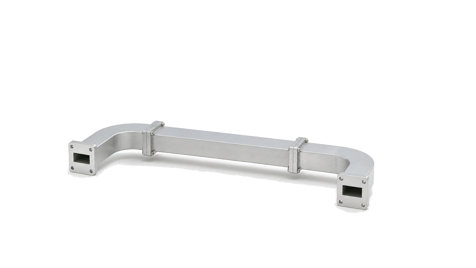
Evidence and configuration boundary
The taxonomy covers multiple interconnect families, but published product evidence is currently narrower. Availability, connector configuration, length and performance must be confirmed against an approved product record. Current documented semi-rigid assemblies include records to 18 GHz and 20 GHz; those records do not qualify every taxonomy branch or custom geometry. A cable-series attenuation curve or connector frequency rating alone cannot qualify the finished assembly.