
Waveguide assemblies
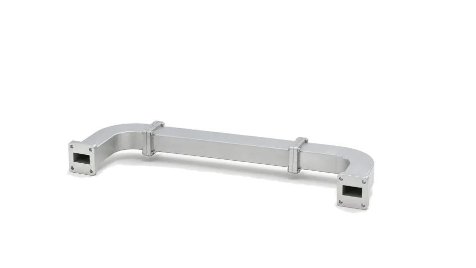
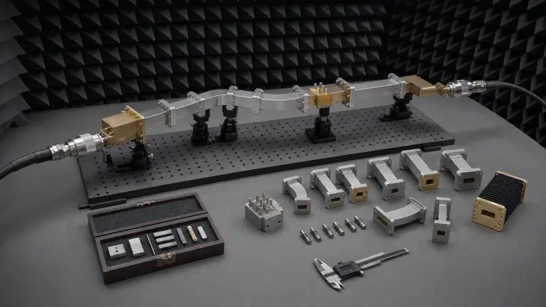
Waveguide assemblies use shaped metal transmission paths for microwave and millimeter-wave signals. They are used when frequency, power level or loss budget makes coaxial cable less suitable, and when flange alignment, bends, twists or transitions must be controlled.
Waveguide path data
Relevant data includes waveguide size or band, flange type, frequency range, insertion loss, return loss or VSWR, power rating, pressure window if used, bend radius, twist angle, length, finish, material and mechanical alignment.
What does the Waveguide Assemblies category cover?
Waveguide assemblies carry microwave and millimeter-wave energy through precision metal paths where coaxial loss or power handling is no longer suitable.
How should hardware in the Waveguide Assemblies category be selected?
Turn a waveguide path into a reviewable specification by controlling band and mode, aperture and flange interfaces, loss and phase, peak and average power, mechanical tolerances, calibration reference planes, uncertainty and acceptance evidence.
- Control the complete path, not a list of nominally compatible parts
- Freeze band, mode and every discontinuity before selecting hardware
- Specify flange geometry, surface condition and assembly repeatability
Which specifications matter when evaluating Waveguide Assemblies?
Relevant data includes waveguide size or band, flange type, frequency range, insertion loss, return loss or VSWR, power rating, pressure window if used, bend radius, twist angle, length, finish, material and mechanical alignment.
How should hardware in the Waveguide Assemblies category be tested and verified?
Specify waveguide and millimeter-wave hardware as one assembled electromagnetic, mechanical and metrology path. Freeze the operating and guard bands, intended propagation mode, waveguide aperture, flange geometry and clocking, polarization, every transition and discontinuity, electrical-loss and phase limits, peak and average power, pressure and temperature, material and surface condition, physical length and support, calibration reference planes, connection repeatability and acceptance evidence. Verify the exact assembled configuration with a band-appropriate calibration and an uncertainty budget.
How to Specify and Verify Waveguide and Millimeter-Wave Hardware