
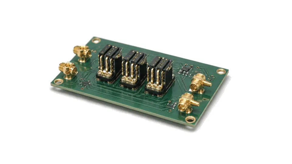
What is a board-to-board RF connector?
A board-to-board RF connector creates a repeatable coaxial or controlled-impedance transition between two printed circuit boards without a cable assembly. It is used in stacked radios, pluggable RF modules, array electronics and test hardware where the boards must be assembled, serviced or replaced independently.
Mechanical tolerance is part of the RF design
The connector cannot be selected from frequency range alone. Nominal and compressed stack height, axial travel, radial and angular misalignment, retention method and mating sequence determine whether the contact remains seated after board and enclosure tolerances accumulate. Blind-mate formats can absorb more positional error; rigid miniature interfaces usually demand tighter datums and a controlled assembly process.
Electrical data must include the PCB launch
Compare characteristic impedance, insertion loss, return loss or VSWR, phase consistency, isolation and power handling over the actual operating band. Package performance does not describe the complete transition: pad geometry, via fence, reference planes, dielectric stack-up and the connector footprint form part of the signal path. For dense arrays, also review channel pitch, crosstalk and the thermal effect of nearby devices.
Verification at the intended stack height
A useful test coupon reproduces both PCB launches, grounding and mechanical compression. Measure the back-to-back path with a calibrated VNA, document the de-embedding method and repeat the sweep at the tolerance limits for height and offset. Mating-cycle checks should look for drift in contact resistance, return loss and phase rather than relying only on visual inspection.
- frequency band, impedance and acceptable insertion/return loss
- nominal stack height, tolerance, travel and permitted misalignment
- PCB material, layer stack, launch geometry and ground strategy
- channel count, pitch, shielding and crosstalk limit
- power, temperature, vibration and mating-cycle requirement
- fixture, calibration plane and acceptance data required
Approval boundary
Datasheet connector data supports a shortlist; release requires a measured transition in the project PCB and mechanical stack. The approved item should therefore be tied to the footprint, assembly datum and test reference plane used by the system.